
Page 283 - Making PIC Microcontroller Instruments and Controllers
P. 283
PROJECi 6 240
BUILDII{G THE TOUCH PAIIEL FNA E
No\r that we know what we need h the way of hardware, let's build a simple touch
frame. The easiest way to do this is to use a Fefabricated rc board with lines on the
back. and lhencul out lhe parls you need lo fit.Aseemb,e
the frame with lhe solderside
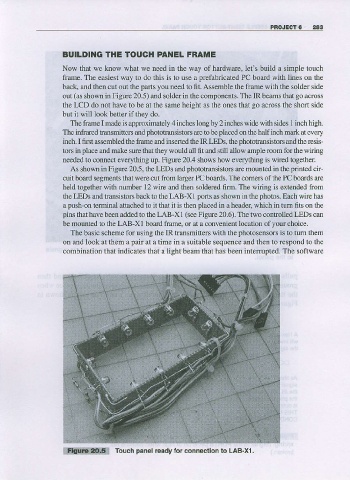
out (as shown in Figue 20.5) and solder in lhe components. The IR beams that go aqoss
the LCD do not have to be at the same height as the ones that go aooss the short side
bul it will look better if they do.
The frame made is approxhEtely 4 iDches long by 2 inches wide widr sides 1 inch high.
I
Tbe in foared t-ansmiflers and photoo?nsistors
ale !o be placed on the half inch mark at every
and
inch. I first assembled lhe frame and inserted the IR LEDS. lhe ohototransistors the resis-
tors in place and make sure thal $ey would aU ftl and sti ll allow ample room for the $ iri ng
ne€ded to connect everything up. Figure 20.4 shows how ever''thing is wired together.
As shown in Figue 20.5, the LEDS and phototra$istors are mounted in the pnnted cir-
cuit board segments that were cut ftom larger PC boards. The comen of the PC boards are
held together with number l2 wie and then solder€d 6Im. The widng is extended ftom
the LEDS aDd trarrsistors back to the LAB-XI porls as showD in the photos. Each wire has
a push-on terminal attached to it that it is then placed in a header, which in tum fits on the
pins that have beer added to tle LAB-XI (se€ Figure 20.6). The two controlled LEDS can
be mount€d to the LAB-X I board ftamq or at a convenient location of your choice.
The basic scheme for using the IR transmitters with the photosensors
is to turn them
on and look at them a pair at a time in a suitable sequence and then ro respond to tho
combination that indicates that a light bearn that has been interupted. The software
W Touch panel ready lor connectlon lo LAB-xl .