
Page 287 - Making PIC Microcontroller Instruments and Controllers
P. 287
FRG'ECT 6 247
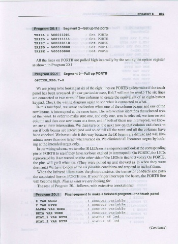
lttblii6dg.!;it!: sesment 2-set up the ports
ERISA = %00011001
fRISB = %00111111
tRlsc = %00000110
tRl€D = %00000000
ERISE = %00000000
AII the lines or PORTB are pulled high intemally by the settirg the oplion register
as shown in Program 20.1
*fmi.!.i.r,:eq;f:: sesment 3-pull up PoRrB
OPIION-REG.7=0
we are going to be looking at six of tbe eight lircs on PORIB to determine if the touch
panel has been accessed. (In our particular case, B.6,7 will not be used.) The six lines
are connected as two rows of four colums to create the equivalent of an eight-button
keypad. Check the wiring diagram again to see what is connecied to what.
In this touchpad, we sense a selection when one of the column beams and one of the
row beams is interupted at the same time. The intersection identifies the selected area
of the panel, ln order to make sure one, and only one, area is selected, we tum on one
column and then one row beam at a time, and if both of then are interrupted, we know
we are at their intersectlon- We then tum on the next row on that column and check to
see if both beams are intenupted and so on till all the rows and all the colunns have
been checked. We have to do it this way because the IR beams are diffuse and will illu-
minate more than one targel when tumed on. We eliminate all incorrect targets by look-
ing at fhe intended target only.
In our widng scheme, we tum the IR Lms on in a sequence and look at the corresponding
pin on PORTB to see if they have not been excited (= intemrpted) on PORTC, the LEDS
represented by 0 are turned on (the other side of the LEDS is tied to 5 volts). On PORTB'
the pins will go 0 when on. (They were pulled up and showed as ls when they were
dormant.) We have to look at the six possible conditions and respond to each of them.
When the infrared illuminates the phototrarsistor, the transistor conducts and pulls
the associated line on PORTB low.Ifyour nnger intefupts the beam, the PORTB line
will become high. fl?dr ir what we arc looking for.
The rest of Program 20. I follows. with exlensive annotatrons:
Final segment to make a linished program-the touch panel
i8ft&lf,dlq:Ei
X VAR WORD counler wariable
Y VAR BYTE counter variabte
AIJPITA VAR WORD counter var:iab1e
BETA VAR WORD counter variabLe
STAT_1 VIIR EYTE
STAT_2 VIIR BYTE