
Page 289 - Managing Global Warming
P. 289
Methane hydrate as a “new energy” 249
and the membrane was installed as shown in Fig. 7.8C. Because the specimens in the
tests were subjected to low temperature and high pressure, rubber membranes conven-
tionally used in triaxial tests were avoided; instead, silicon-type membranes were used
because of their flexibility under low temperature/high pressure conditions and butyl
rubber was used in long-term tests, such as MH dissociation because silicone is to
some degree permeable to methane gas. The inner cell set up is shown in Fig. 7.8D.
7.3.3 Generation of MH and experimental procedure
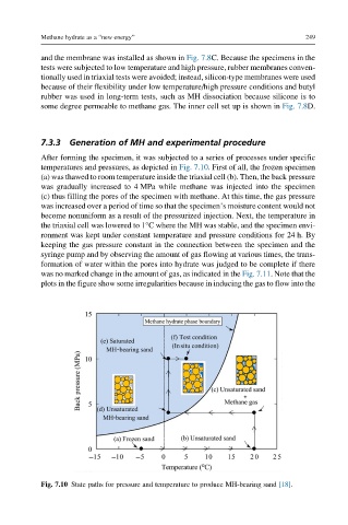
After forming the specimen, it was subjected to a series of processes under specific
temperatures and pressures, as depicted in Fig. 7.10. First of all, the frozen specimen
(a) was thawed to room temperature inside the triaxial cell (b). Then, the back pressure
was gradually increased to 4 MPa while methane was injected into the specimen
(c) thus filling the pores of the specimen with methane. At this time, the gas pressure
was increased over a period of time so that the specimen’s moisture content would not
become nonuniform as a result of the pressurized injection. Next, the temperature in
the triaxial cell was lowered to 1°C where the MH was stable, and the specimen envi-
ronment was kept under constant temperature and pressure conditions for 24 h. By
keeping the gas pressure constant in the connection between the specimen and the
syringe pump and by observing the amount of gas flowing at various times, the trans-
formation of water within the pores into hydrate was judged to be complete if there
was no marked change in the amount of gas, as indicated in the Fig. 7.11. Note that the
plots in the figure show some irregularities because in inducing the gas to flow into the
Fig. 7.10 State paths for pressure and temperature to produce MH-bearing sand [18].