
Page 129 - Manufacturing Engineering and Technology - Kalpakjian, Serope : Schmid, Steven R.
P. 129
Chapter 4 Metal Alloys: Their Structure and Strengthening by Heat Treatment T
Fe atoms C atoms
‘ T
|<\ a if
C atom Fe Fe C
Fe atoms
Austenite Ferrite Martensite Carbon (%) c(nm) a(nm)
O 0.286 0.286
0.20 0.288 0.2858
0.40 0.291 0.2856
(D) (C) (U)
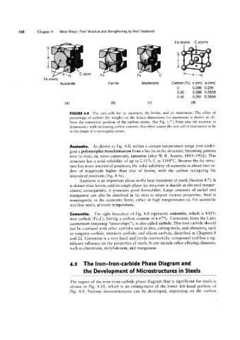
FIGURE 4.9 The unit cells for (a) austenite, (b) ferrite, and (c) martensite. The effect of
percentage of carbon (by weight) on the lattice dimensions for martensite is shown in (d).
Note the interstitial position of the carbon atoms. (See Fig. 1.7.) Note also the increase in
dimension c with increasing carbon content; this effect causes the unit cell of martensite to be
in the shape of a rectangular prism.
Austenite. As shown in Fig. 4.8, Within a certain temperature range iron under~
goes a polymorphic transformation from a bcc to an fcc structure, becoming gamma
iron ('y-iron), or, more commonly, austenite (after W R. Austen, 1843-1902). This
structure has a solid solubility of up to 2.11% C at 1148°C. Because the fcc struc-
ture has more interstitial positions, the solid solubility of austenite is about two or-
ders of magnitude higher than that of ferrite, with the carbon occupying the
interstitial positions (Fig. 4.9a).
Austenite is an important phase in the heat treatment of steels (Section 4.7). It
is denser than ferrite, and its single-phase fcc structure is ductile at elevated temper-
atures; consequently, it possesses good formability. Large amounts of nickel and
manganese can also be dissolved in fcc iron to impart various properties. Steel is
nonmagnetic in the austenitic form, either at high temperatures or, for austenitic
stainless steels, at room temperature.
Cementite. The right boundary of Fig. 4.8 represents cementite, which is 100%
iron carbide (Pe3C), having a carbon content of 6.67%. Cementite, from the Latin
caementum (meaning “stone chips”), is also called carbide. This iron carbide should
not be confused with other carbides used as dies, cutting tools, and abrasives, such
as tungsten carbide, titanium carbide, and silicon carbide, described in Chapters 8
and 22. Cementite is a very hard and brittle intermetallic compound and has a sig-
nificant influence on the properties of steels. It can include other alloying elements,
such as chromium, molybdenum, and manganese.
4.5 The Iron-Iron-carbide Phase Diagram and
the Development of Microstructures in Steels
The region of the iron-iron-carbide phase diagram that is significant for steels is
shown in Fig. 4.10, which is an enlargement of the lower left-hand portion of
Fig. 4.8. Various microstructures can be developed, depending on the carbon