
Page 646 - Manufacturing Engineering and Technology - Kalpakjian, Serope : Schmid, Steven R.
P. 646
Section 23.3 Lathes and Lathe Operations 2
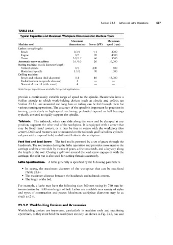
TABLE 23.6
Typical Capacities and Maximum Workpiece Dimensions for Machine Tools
Maximum Maximum
Machine tool dimension (m) Power (kW) speed (rpm)
Lathes (swing/length)
Bench 0.3/1 <1 3000
Engine 3/5 70 4000
Turret 0.5/1.5 60 3000
Automatic screw machines 0.1/0.3 20 10,000
Boring machines (work diameter/length)
Vertical spindle 4/3 200 300
Horizontal spindle 1.5/2 70 1000
Drilling machines
Bench and column (drill diameter) 0.1 - 12,000
10
-
Radial (column to spindle distance) 3 - -
Numerical control (table travel) 4
Note: Larger capacities are available for special applications.
provide a continuously variable range of speed to the spindle. Headstocks have a
hollow spindle to which work-holding devices (such as c/nicks and collets; see
Section 23.3.2) are mounted and long bars or tubing can be fed through them for
various turning operations. The accuracy of the spindle is important for precision in
turning, particularly in high-speed machining; preloaded tapered or ball bearings
typically are used to rigidly support the spindle.
Tailstock. The tailstock, which can slide along the ways and be clamped at any
position, supports the other end of the workpiece. It is equipped with a center that
may be fixed (dead center), or it may be free to rotate with the workpiece (live
center). Drills and reamers can be mounted on the tailstock quill (a hollow cylindri-
cal part with a tapered hole) to drill axial holes in the workpiece.
Feed Rod and Lead Screw. The feed rod is powered by a set of gears through the
headstock. The rod rotates during the lathe operation and provides movement to the
carriage and the cross-slide by means of gears, a friction clutch, and a keyway along
the length of the rod. Closing a split nut around the lead screw engages it with the
carriage; the split nut is also used for cutting threads accurately.
Lathe Specifications. A lathe generally is specified by the following parameters:
° Its swing, the maximum diameter of the workpiece that can be machined
(Table 23.6).
° The maximum distance between the headstock and tailstock centers.
° The length of the bed.
For example, a lathe may have the following size: 360-mm swing by 760 mm be-
tween centers by 1830-mm length of bed. Lathes are available in a variety of styles
and types of construction and power. Maximum workpiece diameters may be as
much as 2 m.
23.3.2 Workholding Devices and Accessories
Workholding devices are important, particularly in machine tools and machining
operations, as they must hold the workpiece securely. As shown in Fig. 23.3, one end