
Page 648 - Manufacturing Engineering and Technology - Kalpakjian, Serope : Schmid, Steven R.
P. 648
m e
Section 23.3 Lathes and Lathe Operations 2
(tapered) Mandrel
, i Mandrel Stralght
mandrel
_ee' 1 M Flat
Workpiece Workpiece Workplece
(a) Solid mandrel (b) Gang mandrel (c) Cone mandrel
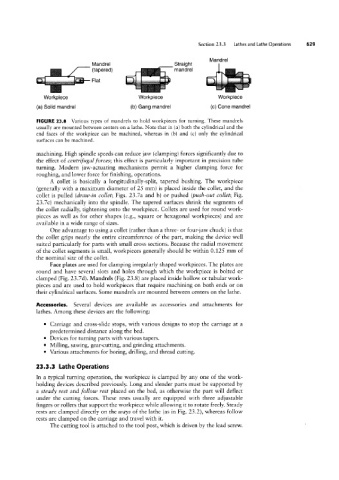
FIGURE 23.8 Various types of mandrels to hold workpieces for turning. These mandrels
usually are mounted between centers on a lathe. Note that in (a) both the cylindrical and the
end faces of the workpiece can be machined, whereas in (b) and (c) only the cylindrical
surfaces can be machined.
machining. High spindle speeds can reduce jaw (clamping) forces significantly due to
the effect of centrifugal forces; this effect is particularly important in precision tube
turning. Modern jaw-actuating mechanisms permit a higher clamping force for
roughing, and lower force for finishing, operations.
A collet is basically a longitudinally-split, tapered bushing. The workpiece
(generally with a maximum diameter of 25 mm) is placed inside the collet, and the
collet is pulled (draw-in collet; Figs. 23.7a and b) or pushed (puslv~o1/it collet; Fig.
23.7c) mechanically into the spindle. The tapered surfaces shrink the segments of
the collet radially, tightening onto the workpiece. Collets are used for round work-
pieces as well as for other shapes (e.g., square or hexagonal workpieces) and are
available in a wide range of sizes.
One advantage to using a collet (rather than a three- or four-jaw chuck) is that
the collet grips nearly the entire circumference of the part, making the device well
suited particularly for parts with small cross sections. Because the radial movement
of the collet segments is small, workpieces generally should be within 0.125 mm of
the nominal size of the collet.
Face plates are used for clamping irregularly shaped workpieces. The plates are
round and have several slots and holes through which the workpiece is bolted or
clamped (Fig. 23.7d). Mandrels (Fig. 23.8) are placed inside hollow or tubular work-
pieces and are used to hold workpieces that require machining on both ends or on
their cylindrical surfaces. Some mandrels are mounted between centers on the lathe.
Accessories. Several devices are available as accessories and attachments for
lathes. Among these devices are the following:
° Carriage and cross-slide stops, with various designs to stop the carriage at a
predetermined distance along the bed.
° Devices for turning parts with various tapers.
° Milling, sawing, gear-cutting, and grinding attachments.
° Various attachments for boring, drilling, and thread cutting.
23.3.3 Lathe Operations
In a typical turning operation, the workpiece is clamped by any one of the work-
holding devices described previously. Long and slender parts must be supported by
a steady rest and follow rest placed on the bed, as otherwise the part will deflect
under the cutting forces. These rests usually are equipped with three adjustable
fingers or rollers that support the workpiece while allowing it to rotate freely. Steady
rests are clamped directly on the ways of the lathe (as in Fig. 23.2), whereas follow
rests are clamped on the carriage and travel with it.
The cutting tool is attached to the tool post, which is driven by the lead screw.