
Page 653 - Manufacturing Engineering and Technology - Kalpakjian, Serope : Schmid, Steven R.
P. 653
l-1 250ld
*§’f
Machining Processes: Turning and Hole Making
3 Chapter 23 ‘i
""""'
t Cam turret
I
Lead 100
24
5
I ,
|
mm S"` “T 4-> -
Turning turret
(8) (D)
12.7
i*---“ ----*i l*'-“75-*I
mm mm
(G) (Cl)
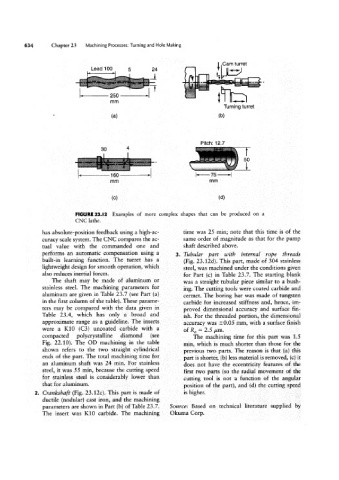
FIGURE 23.|2 Examples of more complex shapes that can be produced on a
CNC lathe.
has absolute-position feedback using a high-ao time was 25 min; note that this time is of the
curacy scale system. The CNC compares the ac- same order of magnitude as that for the pump
tual value with the commanded one and shaft described above.
performs an automatic compensation using a Tubuiar part with internal rope threads
built~in learning function. The turret has a (Fig. 23.12d). This part, made of 304 stainless
lightweight design for smooth operation, which steel, was machined under the conditions given
also reduces inertial forces. for Part (C) in Table 23.7. The staiting blank
The shaft may be made of aluminum or was a straight tubular piece similar to a bush-
stainless steel. The machining parameters for ing. The cutting tools were coated carbide and
aluminum are given in Table 23.7 (see Part (a) cermet. The boring bar was made of tungsten
in the first column of the table). These parame- carbide for increased stiffness and, hence, im-
ters may be compared with the data given in proved dimensional accuracy and surface fin-
Table 23.4, which has only a broad and ish. For the threaded portion, the dimensional
approximate range as a guideline. The inserts accuracy was 10.05 mm, with a surface finish
were a K10 (C3) uncoated carbide with a of Ra = 2.5 um.
compacted polycrystalline diamond (see The machining time for this part was 1.5
Fig. 22.10). The OD machining in the table min, which is much shorter than those for the
shown refers to the two straight cylindrical previous two parts. The reason is that (a) this
ends of the part. The total machining time for part is shorter, (b) less material is removed, (c) it
an aluminum shaft was 24 min. For stainless does not have the eccentricity features of the
steel, it was 55 min, because the cutting speed first two parts (so the radial movement of the
for stainless steel is considerably lower than cutting tool is not a function of the angular
that for aluminum. position of the part), and (cl) the cutting speed
Crankshaft (Fig. 23.12c). This part is made of is higher.
ductile (nodular) cast iron, and the machining
parameters are shown in Part (b) of Table 23.7. Source: Based on technical literature supplied by
The insert was K10 carbide. The machining Ckuma Corp.