
Page 647 - Manufacturing Engineering and Technology - Kalpakjian, Serope : Schmid, Steven R.
P. 647
Spindle nose cap sss,s s i Hood
Chapter 23 Machining Processes: Turning and Hole Making ‘
y
i”is is isssi sssi --_
"
Collet sleeve
Headstock Spring collet Split segments sss, 'V "'*` Workpiece
spindle sleeve (G) Splndle (C)
,,SS=SS
Face plate
(mounted on spindle)
_
_
PM
I, #ug
,f_,
workpiece
‘esss
Jaws Workplece
(bl (U)
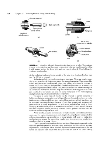
FIGURE 23.1 (a) and (b) Schematic illustrations of a draw-in type of collet. The workpiece
is placed in the collet hole, and the conical surfaces of the collet are forced inward by pulling
it with a draw bar into the sleeve. (c) A push-out type of collet. (d) Work holding of a
workpiece on a face plate.
of the workpiece is clamped to the spindle of the lathe by a chuck, collet, face plate
(see Fig. 23.7d), or mandrel.
A chuck usually is equipped with three or four jaws. Three-jaw chucks gener-
ally have a geared-scroll design that makes the jaws self-centering. They are used for
round workpieces (such as bar stock, pipes, and tubing), which can be centered to
within 0.025 mm. Four-jaw (independent) chucks have jaws that can be moved and
adjusted independently of each other. Thus, they can be used for square, rectangular,
or odd-shaped workpieces. Because they are constructed more ruggedly than three-
jaw chucks, four-jaw chucks are used for heavy workpieces or for work requiring
multiple chuckings where concentricity is important.
The jaws in some types of chucks can be reversed to permit clamping of
hollow workpieces, such as pipes and tubing, either on the outside surfaces or on the
inside surfaces. Also available are jaws made of low-carbon steel (soft jaws) that can
be machined into desired shapes. Because of their low strength and hardness, soft
jaws conform to small irregularities on workpieces and therefore result in better
clamping. Chucks can be power or manually actuated with a chuck wrench. Because
they take longer to operate, manually actuated chucks generally are used only for
toolroom and limited production runs.
Power chucks, actuated pneumatically or hydraulically, are used in automated
equipment for high production rates, including the loading of parts using industrial
robots. Also available are several types of power chucks with lever- or wedge-type
mechanisms to actuate the jaws; these chucks have jaw movements (stroke) that
usually are limited to about 13 mm.
Chucks are available in various designs and sizes. Their selection depends on the
type and speed of operation, workpiece size, production and dimensional accuracy
requirements, and the jaw forces required. By controlling the magnitude of the jaw
forces, an operator can ensure that the part does not slip in the chuck during