
Page 367 - 04. Subyek Engineering Materials - Manufacturing, Engineering and Technology SI 6th Edition - Serope Kalpakjian, Stephen Schmid (2009)
P. 367
Mandrel
rouers
9 7-5
Planetary
me
Retainer Driven Cam
Hammer Workpiece
Die rV'r Q:
4 .QM Q m
(H) (D) r',~rr
“‘ QR Par i
Backer 'Q Workpiece
.eta %
, .s.:z M
'”
2
..
*
1.
5:5
W
\/\/edge Die Qs; Ejector _A,,, ll
~.
!%=i!i~§
‘Lv
lx
W.
Open Swaging Ejecting
position position position
1 2. 3.
(C) (d)
il
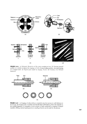
FIGURE l4.l4 (a) Schematic illustration of the rotary-svvaging process. (b) Forming internal
profiles on a tubular workpiece by swaging. (c) A die-closing swaging machine, showing forming
of a stepped shaft. (d) Typical parts made by swaging. Source: (d) Courtesy of ]. Richard
Industries.
;
Tube Die ""»* . Mandrel Ili: mx’
l
ii "
(H) *" (D)
....
:
§ §. -? § -f< '<f~; " - E § ss ‘§§ ‘- as
~§
i
(C)
FIGURE l4.I5 (a) Swaging of tubes without a mandrel; note the increase in wall thickness in
the die gap. (b) Swaging with a mandrel; note that the final wall thickness ofthe tube depends on
the mandrel diameter (c) Examples of cross sections of tubes produced by swaging on shaped
mandrels. Rifling (internal spiral grooves) in small gun barrels can be made by this process.