
Page 365 - 04. Subyek Engineering Materials - Manufacturing, Engineering and Technology SI 6th Edition - Serope Kalpakjian, Stephen Schmid (2009)
P. 365
Section 14.4 Various Forging Operations 345
CASE STUDY l4.l Manufacture of a Stepped Pin by Heading and Piercing Operations
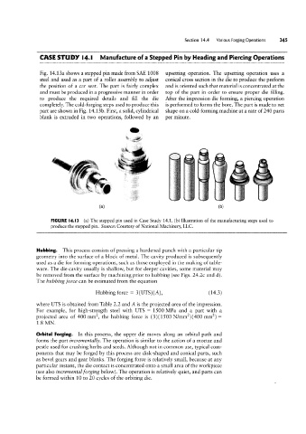
Fig. 14.13a shows a stepped pin made from SAE 1008 upsetting operation. The upsetting operation uses a
steel and used as a part of a roller assembly to adjust conical cross section in the die to produce the preform
the position of a car seat. The part is fairly complex and is oriented such that material is concentrated at the
and must be produced in a progressive manner in order top of the part in order to ensure proper die filling.
to produce the required details and fill the die After the impression-die forming, a piercing operation
completely. The cold-forging steps used to produce this is performed to forms the bore. The part is made to net
part are shown in Fig. 14.13b. First, a solid, cylindrical shape on a cold-forming machine at a rate of 240 parts
blank is extruded in two operations, followed by an per minute.
Q °
r iiii
f I A
(3) T (bl
FIGURE |4.l3 (a) The stepped pin used in Case Study 14.1. (b) Illustration of the manufacturing steps used to
produce the stepped pin. Source: Courtesy of National Machinery, LLC.
Hubbing. This process consists of pressing a hardened punch with a particular tip
geometry into the surface of a block of metal. The cavity produced is subsequently
used as a die for forming operations, such as those employed in the making of table-
ware. The die cavity usually is shallow, but for deeper cavities, some material may
be removed from the surface by machining prior to hubbing (see Figs. 24.2c and d).
The hubbing force can be estimated from the equation
Hubbing force = 3(UTS)(A), (14.3)
where UTS is obtained from Table 2.2 and A is the projected area of the impression.
For example, for high-strength steel with UTS = 1500 MPa and a part with a
projected area of 400 mmz, the hubbing force is (3)(1500 N/mm2)(400 mmz) =
1.8 MN.
Orbital Forging. In this process, the upper die moves along an orbital path and
forms the part incrementally. The operation is similar to the action of a mortar and
pestle used for crushing herbs and seeds. Although not in common use, typical com-
ponents that may be forged by this process are disk-shaped and conical parts, such
as bevel gears and gear blanks. The forging force is relatively small, because at any
particular instant, the die contact is concentrated onto a small area of the workpiece
(see also incremental forging below). The operation is relatively quiet, and parts can
be formed within 10 to 20 cycles of the orbiting die.