
Page 361 - 04. Subyek Engineering Materials - Manufacturing, Engineering and Technology SI 6th Edition - Serope Kalpakjian, Stephen Schmid (2009)
P. 361
Section 14.3 Impression-die and Closed-die Forging 34|
Blank (bar stock)
Edging Fullering Ed gi n g
B'°°""‘Q D 6
y,
A ,i, T vv k'or piece
i.
Die
5
a
Finishing
Trimming
(8) (b) (C)
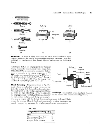
FIGURE I4.7 (a) Stages in forging a connecting rod for an internal combustion engine.
Note the amount of flash required to ensure proper filling of the die cavities. (b) Fullering
and (c) edging operations to distribute the material properly when preshaping the blank for
forging.
including the flash. In hot-forging operations, the actual Before After
forging pressure for most metals typically ranges from ' trimm'ing
550 to 1000 MPa. As an example, assume that the flow
stress of a material at the forging temperature is 700 PunchT Flash
MPa, and a part (such as that shown in Fig. 14.7a) has a (scrap)
projected area (with flash) of 38,000 mmz. Taking a
value of le = 10 from Table 14.2, the forging force
would be F = (10)(700)(38,000) = 266 MN. Trimming die -E
Closed-die Forging. The process shown in Fig. 14.5
Slug Stationary punch
also is referred to as closed-die forging. However, in true
closed-die forging, flash does not form (hence the term
flashless forging), and the workpiece completely fills the
die cavity (see right side of Fig. 14.9b). Consequently, FIGURE |4.8 Trimming flash from a forged part. Note that
the forging pressure is very high, and accurate control of the thin material at the center is removed by punching.
the blank volume and proper die design are essential to
producing a forging with the desired dimensional tolerances. Undersized blanks
prevent the complete filling of the die cavity; conversely, oversized blanks generate
excessive pressures and may cause dies to fail prematurely or the machine to jam.
TABLE l4.2
Range of k Values for Eq. (14.2)
Shape k
Simple shapes, without flash 3-5
Simple shapes, with flash 5-8
Complex shapes, with flash 8-12