
Page 360 - 04. Subyek Engineering Materials - Manufacturing, Engineering and Technology SI 6th Edition - Serope Kalpakjian, Stephen Schmid (2009)
P. 360
F
340 Chapter 14 Metal-Forging Processes and Equipment
Die
Die
(8) (D) (C)
External and internal draft angles
Flash Flib Web Gutter
Parting line
Ci;?:;r
Land Parting
line
Tram une
ld)
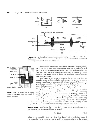
FIGURE I4.5 (a) through (c) Stages in impression-die forging of a solid round billet. Note
the formation of flash, which is excess metal that is subsequently trimmed off. (d) Standard
terminology for various features of a forging die.
The standard terminology for a typical forging die is shown in Fig.
Upper die block
(6F2 or 6(5) 14.5d. Instead of being made as one piece, dies may be made of several
pieces (segmented), including die inserts (Fig. 14.6) and particularly for
Insert (H12)
complex shapes. The inserts can be replaced easily in the case of wear or
Workpiece failure in a particular section of the die and usually are made of stronger
and harder materials.
Insert (H1 2)
The blank to be forged is prepared by (a) cropping from an
extruded or dravvn bar stock; (b) preforming from operations such as
Insert powder metallurgy; (c) casting; or (d) using a preformed blank from a
(6F2 or 6G) prior forging operation. The blank is placed on the lower die, and as the
upper die begins to descend, the blank’s shape gradually changes-as is
Lower die block
shown for the forging of a connecting rod in Fig. 14.7a.
Preforming operations (Figs. 14.7b and c) typically are used to
distribute the material properly into various regions of the blank using
FIGURE l4.6 Die inserts used in forging
an automotive axle housing. (See Section 5.7 simple shaped dies of various contours. In fullering, material is
for die materials.) distributed au/ay from an area. In edging, it is gathered into a localized
area. The part then is formed into the rough shape (say, a connecting
rod) by a process called blocking, using blocker dies. The final opera-
tion is the finishing of the forging in impression dies that give the forging its final
shape. The flash is removed later by a trimming operation (Fig. 14.8).
Forging Force. The forging force, F, required to carry out an impression-die forg-
ing operation can be estimated from the formula
F = leYfA, (14.2)
where le is a multiplying factor obtained from Table 14.2, Yf is the flow stress of
the material at the forging temperature, and A is the projected area of the forging,