
Page 404 - 04. Subyek Engineering Materials - Manufacturing, Engineering and Technology SI 6th Edition - Serope Kalpakjian, Stephen Schmid (2009)
P. 404
<-' `i ;
D
38 Chapter 16 Sheet-Metal Forming Processes and Equipment
, P
F
A r
Die . ____ , A C _L i Fracture
Surface
Penetration
f¢ »;ii; .it , l1
Sheet T Slug
Ca B lai k"
->l i+C|earance
(H)
$ dimension
Penetration depth Burnish
Rollover depth _
Burnish depth
_ i
Sheet
(D
5 5 thickness
"“' £1
§ Q l, Fracture
angle
'-L Burr height i<-dimension
‘d
Breakout
(D)
>~"§i§<?§"
Fiattened portion
Burr
under the punch
A
Q
BUVV h9'Qht1i‘ Dishing C Smooth surface
L E Rough surface
ea s ug 5-»-- C (burnished)
(C)
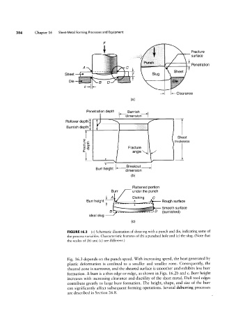
FIGURE |6.2 (a) Schematic illustration of shearing With a punch and die, indicating some of
the process variables. Characteristic features of (b) a punched hole and (c) the slug. (Note that
the scales of (b) and (c) are different.)
Fig. 16.3 depends on the punch speed. With increasing speed, the heat generated by
plastic deformation is confined to a smaller and smaller zone. Consequently, the
sheared zone is narrower, and the sheared surface is smoother and exhibits less burr
formation. A burr is a thin edge or ridge, as shown in Figs. 16.2b and c. Burr height
increases with increasing clearance and ductility of the sheet metal. Dull tool edges
contribute greatly to large burr formation. The height, shape, and size of the burr
can significantly affect subsequent forming operations. Several deburring processes
are described in Section 26.8.