
Page 442 - 04. Subyek Engineering Materials - Manufacturing, Engineering and Technology SI 6th Edition - Serope Kalpakjian, Stephen Schmid (2009)
P. 442
22 Chapter 16 Sheet-Metal Forming Processes and Equipment
Explosiv Water level ii .1
- Work lece Cartridge
Ground level
Water
p Forming die
Standoff - Hold-down E
i_ "ng ‘ i` Workplece (tube)
- Die I
- Vacuum line
- Tank
(D)
p =
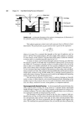
FIGURE I6.49 (a) Schematic illustration of the explosive-forming process. (b) Illustration of
the confined method of the explosive bulging of tubes.
The explosive generates a shock wave with a pressure that is sufficient to form
sheet metals. The peak pressure, p, generated in water is given by the expression
3
R a , (16.15)
where p is in psi, K is a constant that depends on the type of explosive, such as
21.43 >< 106 for TNT (trinitrotoluene), W is the weight of the explosive in newtons,
R is the distance of the explosive from the sheet-metal surface (called the standoff )
in metres, and a is a constant, generally taken to be 1.15.
A variety of shapes can be formed through explosive forming, provided that
the material is ductile at the high rates of deformation characteristic of this process
(see Table 2.4). The process is versatile, as there is virtually no limit to the size of the
sheet or plate. It is suitable particularly for low-quantity production runs of large
parts, such as those used in aerospace applications. Steel plates 25 mm thick and
3.6 m in diameter have been formed by this method, as have tubes with wall thick-
nesses as much as 25 mm. The explosive-forming method also can be used at a much
smaller scale, as shown in Fig. 16.49b. In this case, a cartridge (canned explosive) is
used as the source of energy. The process can be useful in the bulging and expanding
of thin-walled tubes for specialized applications.
The mechanical properties of parts made by explosive forming are basically
similar to those of others made by conventional forming methods. Depending on the
number of parts to be produced, dies may be made of aluminum alloys, steel, ductile
iron, zinc alloys, reinforced concrete, wood, plastics, or composite materials.
Electromagnetically Assisted Forming. In electromagnetically assisted forming, also
called magnetic-pulse forming, the energy stored in a capacitor bank is discharged
rapidly through a magnetic coil. In a typical example, a ring-shaped coil is placed over
a tubular workpiece. The tube is then collapsed by magnetic forces over a solid piece,
thus making the assembly an integral part (Fig. 16.50).
The mechanics of this process is based on the fact that a magnetic field pro-
duced by the coil (Fig. 16.5Oa) crosses the metal tube (which is an electrical conduc-
tor) and generates eddy currents in the tube. In turn, these currents produce their
own magnetic field. The forces produced by the two magnetic fields oppose each
other. The repelling force generated between the coil and the tube then collapses the