
Page 438 - 04. Subyek Engineering Materials - Manufacturing, Engineering and Technology SI 6th Edition - Serope Kalpakjian, Stephen Schmid (2009)
P. 438
8 Chapter 16 Sheet-Metal Forming Processes and Equipment
Mandrel I
(H) (D)
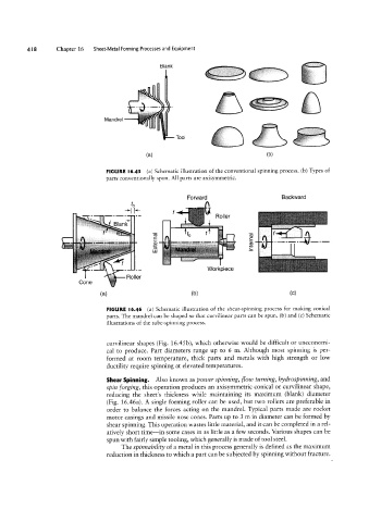
FIGURE |6.45 (a) Schematic illustration of the conventional spinning process. (b) Types of
i.,i Forward Backward
parts conventionally spun. All parts are axisymmetric.
i'l= ,,,,-,=, "“” In -- E C Romer
5 ----
-rl I+
.ifEEE:;f';',;I ,f,,
B'a"‘k
"" - _,__ -_ Workpiece
Cone FiOll9f
(H) (D) (C)
FIGURE l6.46 (a) Schematic illustration of the shear-spinning process for making conical
parts. The mandrel can be shaped so that curvilinear parts can be spun. (b) and (c) Schematic
illustrations of the tube-spinning process.
curvilinear shapes (Fig. 16.45 b), which otherwise would be difficult or uneconomi-
cal to produce. Part diameters range up to 6 m. Although most spinning is per-
formed at room temperature, thick parts and metals with high strength or low
ductility require spinning at elevated temperatures.
Shear Spinning. Also known as pou/er spinning, Hou/ turning, hydrospinning, and
spin forging, this operation produces an axisymmetric conical or curvilinear shape,
reducing the sheet’s thickness while maintaining its maximum (blank) diameter
(Fig. 16.46a). A single forming roller can be used, but two rollers are preferable in
order to balance the forces acting on the mandrel. Typical parts made are rocket
motor casings and missile nose cones. Parts up to 3 m in diameter can be formed by
shear spinning. This operation wastes little material, and it can be completed in a rel-
atively short time--in some cases in as little as a few seconds. Various shapes can be
spun with fairly simple tooling, which generally is made of tool steel.
The spinnability of a metal in this process generally is defined as the maximum
reduction in thickness to which a part can be subjected by spinning without fracture.