
Page 434 - 04. Subyek Engineering Materials - Manufacturing, Engineering and Technology SI 6th Edition - Serope Kalpakjian, Stephen Schmid (2009)
P. 434
4 I4 Chapter 16 Sheet-Metal Forming Processes and Equipment
Before After Before After
Punch
Flexible
Pa
<1
(D)
(H) Tff ' (C)
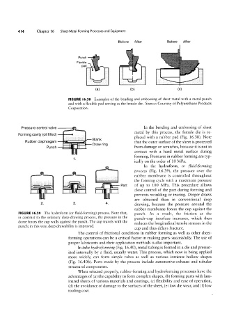
FIGURE l6.38 Examples of the bending and embossing of sheet metal with a metal punch
and with a flexible pad serving as the female die. Source: Courtesy of Polyurethane Products
Corporation.
Forming cavity (oil filled) i t metal by this process, the female die is re-
In the bending and embossing of sheet
Pressure-control valve
contact with a hard metal surface during
la-
Rubber diaphragam i - -3 Elank 9 placed with a rubber pad (Fig. 16.38). Note
that the outer surface of the sheet is protected
punch =: gin
al'T'li rm
from damage or scratches, because it is not in
forming. Pressures in rubber forming are typ-
1.
ically on the order of 10 MPa.
or fluid-forming
In the hydroform,
process (Pig. 16.39), the pressure over the
the forming cycle with a maximum pressure
of up to 100 MPa. This procedure allows
close control of the part during forming and
| R ,| R l Ii | l Part rubber membrane is controlled throughout
prevents wrinkling or tearing. Deeper draws
are obtained than in conventional deep
2. 3. 4. drawing, because the pressure around the
rubber membrane forces the cup against the
FIGURE |6.39 The hydroform (or fluid-forming) process. Note that, punch. As a result, the friction at the
in contrast to the ordinary deep-drawing process, the pressure in the punch-cup interface increases, which then
dome forces the cup walls against the punch. The cup travels with the reduces the longitudinal tensile stresses in the
punch; in this way, deep drawability is improved.
cup and thus delays fracture.
The control of frictional conditions in rubber forming as well as other sheet-
forming operations can be a critical factor in making parts successfully. The use of
proper lubricants and their application methods is also important.
In tube hydroforming (Fig. 16.40), metal tubing is formed in a die and pressur-
ized internally by a fluid, usually water. This process, which now is being applied
more widely, can form simple tubes as well as various intricate hollow shapes
(Fig. 16.40b). Parts made by the process include automotive-exhaust and tubular
structural components.
When selected properly, rubber-forming and hydroforming processes have the
advantages of (a) the capability to form complex shapes, lb) forming parts with lam-
inated sheets of various materials and coatings, (c) flexibility and ease of operation,
(d) the avoidance of damage to the surfaces of the sheet, (e) low die wear, and (f) low
tooling cost.