
Page 431 - 04. Subyek Engineering Materials - Manufacturing, Engineering and Technology SI 6th Edition - Serope Kalpakjian, Stephen Schmid (2009)
P. 431
Section 16.7 Deep Drawing
Bead ,_ - - _ Blan K
edge after
drawing Bend and
l
u///// » D
Punch L- origina| straighten | dxf’
B'a"k*‘°'def il/ blank o I 9
§ 3 edge - ‘ _ __
~e llll\\ \\ Q
D|e ' - Z » » I
Bead GYO |'T:|||'1Ol`
stram
'_ _______ J
Q
(H) (D) (C)
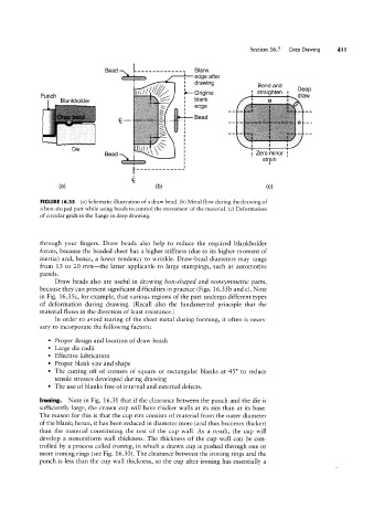
FIGURE l6.35 (a) Schematic illustration of a draw bead. (b) Metal flow during the drawing of
a box-shaped part while using beads to control the movement of the material. (c) Deformation
of circular grids in the flange in deep drawing.
through your fingers. Draw beads also help to reduce the required blankholder
forces, because the beaded sheet has a higher stiffness (due to its higher moment of
inertia) and, hence, a lower tendency to wrinkle. Draw-bead diameters may range
from 13 to 20 mm-the latter applicable to large stampings, such as automotive
panels.
Draw beads also are useful in drawing box-shaped and nonsymmetric parts,
because they can present significant difficulties in practice (Figs. 16.35 b and c). Note
in Fig. 16.35c, for example, that various regions of the part undergo different types
of deformation during drawing. (Recall also the fundamental principle that the
material flows in the direction of least resistance.)
In order to avoid tearing of the sheet metal during forming, it often is neces-
sary to incorporate the following factors:
¢ Proper design and location of draw beads
° Large die radii
° Effective lubrication
° Proper blank size and shape
° The cutting off of corners of square or rectangular blanks at 45° to reduce
tensile stresses developed during drawing
° The use of blanks free of internal and external defects.
Ironing. Note in Fig. 16.31 that if the clearance between the punch and the die is
sufficiently large, the drawn cup will have thicker walls at its rim than at its base.
The reason for this is that the cup rim consists of material from the outer diameter
of the blank; hence, it has been reduced in diameter more (and thus becomes thicker)
than the material constituting the rest of the cup wall. As a result, the cup will
develop a nonuniform wall thickness. The thickness of the cup wall can be con-
trolled by a process called ironing, in which a drawn cup is pushed through one or
more ironing rings (see Fig. 16.30). The clearance between the ironing rings and the
punch is less than the cup wall thickness, so the cup after ironing has essentially a