
Page 429 - 04. Subyek Engineering Materials - Manufacturing, Engineering and Technology SI 6th Edition - Serope Kalpakjian, Stephen Schmid (2009)
P. 429
Section 16.7 Deep Drawing 409
capable of undergoing a reduction in width due to a reduction in
diameter and (b) must also resist thinning under the longitudinal ten- R : él
s
sile stresses in the cup wall. Deep drau/ability generally is expressed S Sf
by the limiting drawing ratio (LDR) as
Maximum blank diameter DO
= = . 16.10
LDR Punch diameter DI, ( )
Whether a sheet metal can be deep drawn successfully into a round
cup-shaped part has been found to be a function of the normal
anisotropy, R (also called plastic anisotropy), of the sheet metal.
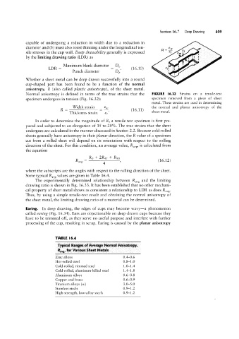
Normal anisotropy is defined in terms of the true strains that the FIGURE |6.32 Strains on a tensile-test
specimen undergoes in tension (Fig. 16.32): specimen removed from a piece of sheet
metal. These strains are used in determining
Width strain sw the normal and planar anisotropy of the
R . 1 6. 1 1
Thickness strain s, ( ) sheet metal.
In order to determine the magnitude of R, a tensile-test specimen is first pre-
pared and subjected to an elongation of 15 to 20%. The true strains that the sheet
undergoes are calculated in the manner discussed in Section 2.2. Because cold-rolled
sheets generally have anisotropy in their planar direction, the R value of a specimen
cut from a rolled sheet will depend on its orientation with respect to the rolling
direction of the sheet. For this condition, an average value, Ravg, is calculated from
the equation
_ R0 + 2R45 + R90
Ravg _ 4 s (16.12)
where the subscripts are the angles with respect to the rolling direction of the sheet.
Some typical Ravg values are given in Table 16.4.
The experimentally determined relationship between Ravg and the limiting
drawing ratio is shown in Fig. 16.33. lt has been established that no other mechani-
cal property of sheet metal shows as consistent a relationship to LDR as does Ravg.
Thus, by using a simple tensile-test result and obtaining the normal anisotropy of
the sheet metal, the limiting drawing ratio of a material can be determined.
Earing. In deep drawing, the edges of cups may become wavy-a phenomenon
called earing (Fig. 16.34). Ears are objectionable on deep-drawn cups because they
have to be trimmed off, as they serve no useful purpose and interfere with further
processing of the cup, resulting in scrap. Earing is caused by the planar anisotropy
TABLE l6.4
Typical Ranges of Average Normal Anisotrnpy,
Rays, fur Various Sheet Metals
Zinc alloys 0.4-0.6
Hot-rolled steel 0.8-1.0
Cold-rolled, rimmed steel 1.0-1.4
Cold-rolled, aluminum-killed steel 1.4-1.8
Aluminum alloys 0.6-0.8
Copper and brass 0.6-0.9
Titanium alloys (cz) 3.0-5.0
Stainless steels 0.9-1.2
High-strength, low-alloy steels 0.9-1.2