
Page 430 - 04. Subyek Engineering Materials - Manufacturing, Engineering and Technology SI 6th Edition - Serope Kalpakjian, Stephen Schmid (2009)
P. 430
0 Chapter 16 Sheet-Metal Forming Processes and Equipment
Coppell
brass, Titanium
aluminum Sf@@;e»~e'
Zinc
directional R values from the equation
O2 0.4 0.6 `I.O 2.0 4.0 6.0
Average strain ratio (Ravg)
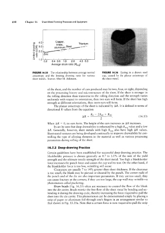
FIGURE I6 33 The relationship between average normal FIGURE |6.34 Earing in a drawn steel
anisotropy and the limiting drawing ratio for various cup, caused by the planar anisotropy of
sheet metals Source: After M. Atkinson. the sheet metal.
of the sheet, and the number of ears produced may be two, four, or eight, depending
on the processing history and microstructure of the sheet. If the sheet is stronger in
the rolling direction than transverse to the rolling direction and the strength varies
uniformly with respect to orientation, then two ears will form. If the sheet has high
strength at different orientations, then more ears will form.
The planar anisotropy of the sheet is indicated by AR. It is defined in terms of
R - ZR R
AR = (16.13)
When AR = 0, no ears form. The height ofthe ears increases as AR increases.
It can be seen that deep drawability is enhanced by a high Ravg value and a low
AR. Generally, however, sheet metals with high Ravg also have high AR values.
Sheet-metal textures are being developed continually to improve drawability by con-
trolling the type of alloying elements in the material as well as various processing
parameters during rolling of the sheet.
l6.7.2 Deep-drawing Practice
Certain guidelines have been established for successful deep-drawing practice. The
blankholder pressure is chosen generally as 0.7 to 1.0% of the sum of the yield
strength and the ultimate tensile strength of the sheet metal. Too high a blankholder
force increases the punch force and causes the cup wall to tear. On the other hand, if
the blankholder force is too low, wrinkling will occur.
Clearances are usually 7 to 14% greater than sheet thickness. If the clearance
is too small, the blank may be pierced or sheared by the punch. The corner radii of
the punch and of the die are also important parameters. lf they are too small, they
can cause fracture at the corners; if they are too large, the cup wall may wrinkle-a
phenomenon called puckering.
Draw beads (Fig. 1635) often are necessary to control the flow of the blank
into the die cavity. Beads restrict the free flow of the sheet metal by bending and un-
bending it during the drawing cycle, thereby increasing the force required to pull the
sheet into the die cavity. This phenomenon can be demonstrated simply by placing a
strip of paper or aluminum foil through one’s fingers in an arrangement similar to
that shown in Fig. 13.35a. Note that a certain force is now required to pull the strip