
Page 435 - 04. Subyek Engineering Materials - Manufacturing, Engineering and Technology SI 6th Edition - Serope Kalpakjian, Stephen Schmid (2009)
P. 435
die
‘fjf
if Centering Section 16.8 Rubber Forming and Hydroforming 4l5
eee,,e eeeeeeeeeeeeeee
PWC” ~~== e e it
Bottom Die-holder
Slide plate
plate
~ 1
5 if
ee'e
H0r;Z0ma|
TOD die
yy
`i _.`,
holder
I.. t , 5.,. 5, ig. Cylinder
bfackel
.. ' " if . ll'l` i. .pp L, Die_ho|der
Bed plate Hydroformed part
(al (bl
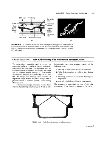
FIGURE l6.40 (a) Schematic illustration of the tube-hydroforming process. (b) Example of
tube-hydroformed parts. Automotive-exhaust and structural components, bicycle frames, and
hydraulic and pneumatic fittings are produced through tube hydroforming. Source: Courtesy
of Schuler GmBH.
CASE STUDY l6.2 Tube Hydroforming of an Automotive Radiator Closure
The conventional assembly used to support an hydroforming processing sequence consists of the
automotive radiator, or radiator closure, is construc- following steps:
ted through the stamping of components that are
I. Bending of tube to the desired configuration
subsequently Welded together. To simplify the design
and to achieve weight savings, a hydroformed 2. Tube hydroforming to achieve the desired
assembly was designed, as shown in Fig. 16.41. Note Shape
that the design uses varying cross sections, an 3. Finishing operations, such as end shearing and
important design feature to reduce weight and to inspection
provide surfaces to facilitate assembly and mounting 4_ Assembly, including Welding of Componenw
of the radiator. _
Tube hydroforming is a versatile process that is The Sequence of Opefatlons OH 0116 Of the tube
capable of producing complex shapes. A typical tube components of the closure is shown in Fig. 16.42.
,... ...in
~ '
FIGURE l6.4l Hydroformed automotive radiator closure.
(continued )