
Page 436 - 04. Subyek Engineering Materials - Manufacturing, Engineering and Technology SI 6th Edition - Serope Kalpakjian, Stephen Schmid (2009)
P. 436
4 I6 Chapter 16 Sheet-Metal Forming Processes and Equipment
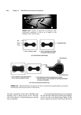
FIGURE l6.42 Sequence of operations in producing a tube-
hydroformed component: (1) tube as cut to length; (2) after
bending; (3) after hydroforming.
Die
Tube Expanded tube
Fluid
1. Die is closed on tube. 2. Tube is expanded and takes
the shape of the die cavity.
(a) Conventional hydroforming
Die pressure
Die closing force
1. Die is partially closed; low pressure
2 Die closing force and low pressure act to force
forces lube to partially fi" Cavity I tube into cavity; corner stresses are bending dominated
to improve formability
(b) Pressure sequence hydroforming
FIGURE l6.43 Schematic illustration of expansion of a tube to a desired cross section through (a) conventional
hydroforming and (b) pressure sequence hydroforming.
The tube, constructed of steel with a 300 MPa yield Conventional hydroforming involves closing the
strength, is bent to shape (see Fig. 1627). The bent die onto the tube, followed by internal pressurization
tube is then placed in a hydroforming press and end to force the tube to the desired shape. Figure 16.4341
caps are attached. shows a typical cross section. Note that as the tube is