
Page 617 - 04. Subyek Engineering Materials - Manufacturing, Engineering and Technology SI 6th Edition - Serope Kalpakjian, Stephen Schmid (2009)
P. 617
598 Chapter 22 Cutting-Tool Materials and Cutting Fluids
method has led to the development of inserts, which are individ-
ual cutting tools With several cutting points (Fig. 22.2). A square
insert has eight cutting points, and a triangular insert has six.
Inserts usually are clamped on the tool/colder with various lock-
ing mechanisms (Fig. 22.3). Although not used as commonly,
inserts also may be brazed to the tool shank, but this practice
has largely been abandoned.
Clamping is the preferred method of securing an insert
because each insert has a number of cutting points and, after
one edge is worn, it is indexed (rotated in its holder) to make
another cutting point available. ln addition to the examples in
this figure, a Wide variety of other toolholders is available for
specific applications, including those with quick insertion and
removal features.
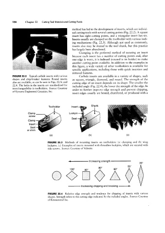
FIGURE 22.2 Typical carbide inserts with various Carbide inserts are available in a variety of shapes, such
shapes and chip-breaker features: Round inserts as square, triangle, diamond, and round. The strength of the
also are available, as can be seen in Figs. 22.3c and cutting edge of an insert depends on its shape. The smaller the
22.4. The holes in the inserts are standardized for included angle (Fig. 22.4), the lower the strength of the edge. In
interchangeability in toolholders. Source: Courtesy order to further improve edge strength and prevent chipping,
of Kyocera Engineered Ceramics, Inc.
insert edges usually are honed, chamfered, or produced with a
Shank
Toolholder Insert .
Clamp Lockpin
screw
Seat
Clamp
Insert a:»=.§4“
Seat
or shim
(H) (D) (C)
FIGURE 22.3 Methods of mounting inserts on toolholders: (a) clamping and (b) wing
lockpins. (c) Examples of inserts mounted with threadless lockpins, which are secured with
side screws. Source: Courtesy of Valenite.
th---1
ncreaslng t s reng 350
0 55° S
100° 90° Bio 60° 3
Increasing chipping and breaking L-->
FIGURE 22.4 Relative edge strength and tendency for chipping of inserts with various
shapes. Strength refers to the cutting edge indicated by the included angles. Source: Courtesy
of Kennametal Inc.