
Page 618 - 04. Subyek Engineering Materials - Manufacturing, Engineering and Technology SI 6th Edition - Serope Kalpakjian, Stephen Schmid (2009)
P. 618
Section 22.4 Carbides 599
_gg §
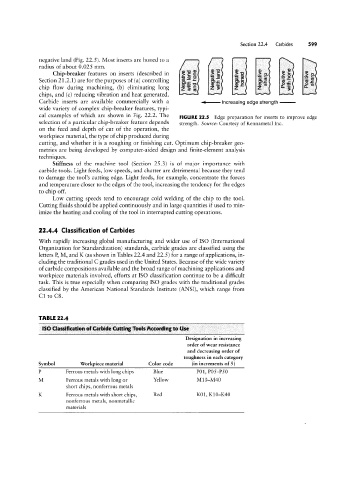
negative land (Fig. 22.5). Most inserts are honed to a
radius of about 0.025 mm. GJ
Chip-breaker features on inserts (described in ii E 3 9 £5 39
Section 2l.2.1) are for the purposes of (a) controlling ‘gg g Lété gs g §,§ IL’-"-.C 9:-'CU
‘-°_~::
0 tn
chip flow during machining, (b) eliminating long § gf! Z `§ Z J: E in ,§'_=?:s EL
3
chips, and (c) reducing vibration and heat generated.
Carbide inserts are available commercially with a <l Increasing edge strength
wide variety of complex chip-breaker features, typi-
cal examples of which are shown in Fig. 22.2. The FIGURE 22.5 Edge preparation for inserts to improve edge
selection of a particular chip-breaker feature depends strength. Source: Courtesy of Kennametal Inc.
on the feed and depth of cut of the operation, the
workpiece material, the type of chip produced during
cutting, and whether it is a roughing or finishing cut. Optimum chip-breaker geo-
metries are being developed by computer-aided design and finite-element analysis
techniques.
Stiffness of the machine tool (Section 25.3) is of major importance with
carbide tools. Light feeds, low speeds, and chatter are detrimental because they tend
to damage the tool’s cutting edge. Light feeds, for example, concentrate the forces
and temperature closer to the edges of the tool, increasing the tendency for the edges
to chip off.
Low cutting speeds tend to encourage cold welding of the chip to the tool.
Cutting fluids should be applied continuously and in large quantities if used to min-
imize the heating and cooling of the tool in interrupted cutting operations.
22.4.4 Classification of Carbides
With rapidly increasing global manufacturing and wider use of ISO (International
Organization for Standardization) standards, carbide grades are classified using the
letters P, M, and K (as shown in Tables 22.4 and 22.5 ) for a range of applications, in-
cluding the traditional C grades used in the United States. Because of the wide variety
of carbide compositions available and the broad range of machining applications and
workpiece materials involved, efforts at ISO classification continue to be a difficult
task. This is true especially when comparing ISO grades with the traditional grades
classified by the American National Standards Institute (ANSI), which range from
C1 to C8.
TABLE 22.4
ISO Classification of Carbide Cutting Tunis According to Use
Designation in increasing
order of wear resistance
and decreasing order of
toughness in each category
Symbol Workpiece material Color code (in increments of 5 )
P Ferrous metals with long chips Blue P01, P05-P50
M Ferrous metals with long or Yellow M10-M40
short chips, nonferrous metals
K Ferrous metals with short chips, Red K01, KIO-K40
nonferrous metals, nonmetallic
materials