
Page 131 - Marine Structural Design
P. 131
Chapter 6 Wshore Structural Analysis 107
6.3.2 Stiffness Matrix for 2D Beam Elements
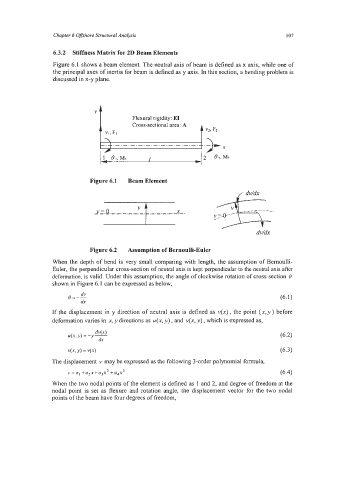
Figure 6.1 shows a beam element. The neutral axis of beam is defined as x axis, while one of
the principal axes of inertia for beam is defined as y axis. In this section, a bending problem is
discussed in x-y plane.
Y
Flexural rigidity: E1
Cross-sectional area: A
A ~2. F2
'' %FI
\
-. .-.-._._._._._._._._._.
P
1 8i.Mi I
Figure 6.1 Beam Element
J!!_=..o
dv/dx
Figure 6.2 Assumption of Bernoulli-Euler
When the depth of bend is very small comparing with length, the assumption of Bemoulli-
Euler, the perpendicular cross-section of neutral axis is kept perpendicular to the neutral axis after
deformation, is valid. Under this assumption, the angle of clockwise rotation of cross-section 6
shown in Figure 6.1 can be expressed as below,
If the displacement in y direction of neutral axis is defined as V(X) , the point (x,y ) before
deformation varies in x, y directions as u(x, y) , and v(x, y) , which is expressed as,
4% Y) = v(4 (6.3)
The displacement v may be expressed as the following 3-order polynomial formula,
v=a, +a2x+a3x2 +a4? (6.4)
When the two nodal points of the element is defined as 1 and 2, and degree of freedom at the
nodal point is set as flexure and rotation angle, the displacement vector for the two nodal
points of the beam have four degrees of freedom,