
Page 194 - Marine Structural Design
P. 194
170 Part 11 Lntimate Strength
PE = E1/12 (9.6)
and f(q) represents the deflection due to lateral load q.
It is assumed that the member is subjected to an axial compression, end moments, and linearly
distributed lateral loads as illustrated in Figure 9.12. If both ends are simply supported, Eq.
(9.3) reduces to:
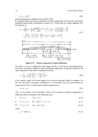
Figure 9.13 Plastic Component of Lateral Deflection
The suffix e in Eq. (9.7) implies the elastic range, and Eq. (9.7) gives the relationship between
axial force and lateral deflection until plastification takes place. Using this deflection, the
mean compressive axial strain is expressed as follows:
In the inelastic region, the flexural rigidity is not uniform along the length of a member. For
this case, the plastic component of deflectionwp is introduced. Then, the total deflection is
expressed as the sum of elastic and the plastic components as:
(9.9)
w=w,+w P
Here, wp is evaluated as the cumulative value of the increments of plastic components of
deflection which are assumed in the following forms
I OlX(l, dw, = cx/l, (9.10)
II Zl lx(l, +Ip dw, =c(ylx’ +y2x+y,) (9.1 1)
111 r, +Ip I I1 dw, = c(l -&, (9.12)
x
(9.13)