
Page 195 - Marine Structural Design
P. 195
Chapter 9 Buckling and Local Buckling of Tubular Members 171
Y2 = (411, +4)/4 411, (9.14)
ys = -1, 1/21,1, 1 I, (9.15)
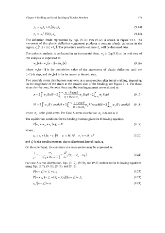
The deflection mode represented by Eqs. (9.10) thru (9.12) is shown in Figure 9.13. The
increment of this plastic deflection component produces a constant plastic curvature in the
region, 1, (f, I n I I, +I, ). The procedure used to estimate 1, will be discussed later.
The inelastic analysis is performed in an incremental form. W, in Eq49.9) at the n-th step of
this analysis, is expressed as:
w,(n)= w,(n-I)+dw,(n) (9.16)
where w,(n -1) is the cumulative value of the increments of plastic deflection until the
(n-1)-th step, and dwp(n) is the increment at the n-th step.
Two possible stress distributions may exist at a cross-section after initial yielding, depending
on the magnitude of the strain at the tension side of the bending; see Figure 9.14. For these
stress distributions, the axial force and the bending moment are evaluated as:
1 v+Rcosa, -2
p=2 'oyRtd6+2 -02 v+Rcos6 cy Rtd6 - 2 1 oy Rtd6 (9.17)
-02 7 +cos 6
A4 = 2 %' cy RZt COS &to + 2 R 2t cos €ti6 - 2 1- oy 't cos &t6 (9.1 8)
R
al
where cy is the yield stress. For Case A stress distribution a2 is taken as 0.
The equilibrium condition for the bending moment gives the following equation.
p(We + W, +eo)+ Q = M (9.19)
where,
e, = ei +z, (ei -ej )/I, e, = M,/P, ej = -M~/P (9.20)
and Q is the bending moment due to distributed lateral loads, q.
On the other hand, the curvature at a cross-section may be expressed as:
1
-=- OY - -(We d2 + w, - wo) (9.21)
p E(v + Rcosa,) - riX2
For case A stress distribution, Eqs. (9.17), (9.19), and (9.21) reduce to the following equations
using Eqs. (9.7), (9.10), (9.1 l), and (9.12):
P(v+A)=f2 +C,V (9.22)
(9.23)
(9.24)