
Page 410 - Marine Structural Design
P. 410
386 Pari III Fatigue and Fracture
directions. This approach is generally prohibitively complex. Therefore, simplified S-N
classification is used based on the rule of thumb in engineering applications.
When classifylng the weld's structural details in large, complex structural systems from a
series of design drawings, it is important to:
Consider each weld individually
Consider each direction of applied stress
Evaluate all possible cracking locations, because each may yield a different classification
Consider any possible stress concentration effects
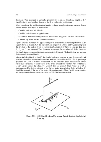
Figures 20.3 and 20.4 show two typical examples of details found in a floating structure. In the
section shown in Figure 20.3, the classifications range from C to F2 and W, depending upon
the direction of the applied stress. In these examples, stresses in the three principal directions
S, , S, and S, , are not equal. Thus the design stress range for each class will differ. However,
for simple design purposes, the maximum principal stress and F2 classification are assigned
for the overall structural details.
It is particularly difficult to classify the details that have a hole and to identify potential crack
locations. Holes in a continuous longitudinal weld are covered in the UK DEn fatigue design
guidelines as Class F, without requirement for an additional stress concentration factor.
However, a web should be incorporated to this detail. The end of a web butt weld at the hole is
a more severe detail that should be ground. For the ground detail, Class E or D is
recommended. Due to the presence of the hole, a stress concentration factor of 2.2 or 2.4
should be included. If the end of the butt weld is not ground, a Class F or F2 curve, together
with the geometrical stress concentration factor (2.2-2.4), is recommended.
Figure 20.3 S-N Classification of Structural Details Subjected to Triaxial
Loading