
Page 409 - Marine Structural Design
P. 409
Chapter 20 Spectral Fatigue Analysis and Design 385
In addition to the weld toe, which is the most usual site for fatigue cracking to occur, all load
carrying fillet welds and partial penetration butt welds must be evaluated to assess possible
weld throat failure. To avoid this type of failure, it is necessary to ensure that these joints are
adequately dimensioned. This may be achieved using the Class W design S-N curve. One
should note that the maximum shear stress range is associated with the class W design S-N
curve.
Structural Details
The UK DEn fatigue design and assessment guidelines provide sketches, which provide
assistance in the S-N classification of structural details. According to UK DEn (1990)
guidelines, joints are subdivided into the following types:
Metal free from welding
Continuous welds essentially parallel to the direction of applied stress
Transverse butt welds
Weld attachments on the surface of a stressed member
Load-carrying fillet and T butt welds
Details in welded girders
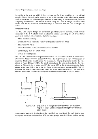
The UK DEn Curves were developed based on small test specimens. In the S-N classification
of structural details, the users first carefully relate the fatigue stress in tests with the stress of
structural details under consideration. For example, the fatigue stress in the test for the weld
shown in Figure 20.2a, would be the tensile stress, S, on the cross-section, but for the weld
shown in Figure 20.2b, it would be SCF S , where SCF is the stress concentration factor
caused by the hole. This is due to the fact that at point x, the stress near the weld is SCF S .
However, for a small cutout in Figure 20.4c, the stress concentration due to the small hole
shall not be included since micro-structural effects have been included in the S-N curves.
ts
C
Figure 20.2 Explanation of Fatigue Stress When Weld is Situated in
Region of Stress Concentration Resulting from Structure’s
Gross Shape
Theoretically, structural details should be classified and considered for each loading step
throughout the fatigue analysis since different loading steps result in different applied loading