
Page 419 - Marine Structural Design
P. 419
Chapter 21 Application of Fracture Mechanics 395
The original failure assessment diagram (FAD) was developed by the U.K. Central Electricity
Generating Board (CEGB). This FAD is shown in Figure 21.2. The CEGB approach (Milne et
al., 1986, 1988; Kanninen and Popelar, 1985) addressed post-yield fracture by an interpolation
formula between two limiting cases: linear elastic fracture and plastic collapse. The
interpolation formula, called the failure assessment or R6 curve (see Fig. 2 1.2) is:
(2 1.7)
KR=L?--- I~[s~c(o.~zs,)]
-
The right-hand side of Eq. (21.7) is the plastic correction to the small-scale yielding prediction.
The CEGB R6 curve in Figure 21.2 may be interpreted as follows: A structural component is
safe if the point W describing its state falls inside of the R6 curve. The component fails if the
point W is on or above the R6 curve. The utilisation factor on load is OW/OF, where point F is
on the R6 curve and point 0 is in the origin.
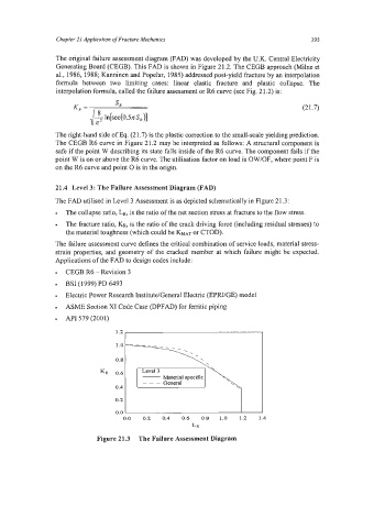
21.4 Level 3: The Failure Assessment Diagram (FAD)
The FAD utilised in Level 3 Assessment is as depicted schematically in Figure 21.3:
The collapse ratio, LR, is the ratio of the net section stress at fracture to the flow stress.
The fracture ratio, KR, is the ratio of the crack driving force (including residual stresses) to
the material toughness (which could be KMAT or CTOD).
The failure assessment curve defines the critical combination of service loads, material stress-
strain properties, and geometry of the cracked member at which failure might be expected.
Applications of the FAD to design codes include:
CEGB R6 - Revision 3
BSI (1 999) PD 6493
Electric Power Research Institute/General Electric (EPRVGE) model
ASME Section XI Code Case (DPFAD) for ferritic piping
API 579 (2001)
.
0.8
KR
Material specific
0.4
0.2 1
0.0 0.2 0.4 0.6 0.8 1.0 1.2 1.4
LR
Figure 21.3 The Failure Assessment Diagram