
Page 72 - Marine Structural Design
P. 72
48 Part I Strueturn1 Design Principles
Hydrodynamic forces
Motion induced hydrostatic restoring forces
Motion induced structural inertial loads and internal tank sloshing loads
Mooring and riser forces
Shear forces, bending moments, and torsional moments like structural boundary
conditions
5. Performing structural analysis to calculate stress FRF H (0, a&[) for each wave frequency
a, wave heading ak, and loading pattern AI. Each combination of (a, a&) forms a
different loading case in structural analysis. The finite element method or other simplified
structural analysis can be applied for the various levels of analysis, see Chapter 6. For
example, to analyze the strength of deck and bottom plating in the hull-girder strength
level, calculations using vertical bending moment and sectional modulus can provide
satisfactory results.
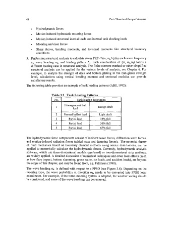
The following table provides an example of tank loading patterns (ABS, 1992):
No. Tank loading descriDtion
Homogeneous Full Design draft
load
2 Normal ballast load Light draft
3 Partial load 33% full
4 Partial load 50% full
I 5 I Partialload I 67% full I
The hydrodynamic force components consist of incident wave forces, diffraction wave forces,
and motion-induced radiation forces (added mass and damping forces). The potential theory
of fluid mechanics based on boundary element methods using source distributions, can be
applied to numerically calculate the hydrodynamic forces. Currently, hydrodynamic analysis
software, which use three-dimensional models (preferred) or two-dimensional strip methods,
are widely applied. A detailed discussion of numerical techniques and other load effects (such
as bow flare impact, bottom slamming, green water, ice loads, and accident loads), are beyond
the scope of this chapter, and may be found from, e.g. Faltinsen (1990).
The wave heading ak is defined with respect to a FPSO (see Figure 3.6). Depending on the
mooring type, the wave probability at direction ak, needs to be converted into FPSO local
coordinates. For example, if the turret-mooring system is adopted, the weather vaning should
be considered, and some of the wave headings can be removed.