
Page 73 - Marine Structural Design
P. 73
Chapter 3 Loah and Dynamic Response for offshore Structures 49
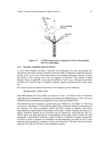
Figure 3.6 A FPSO System and Coordinates for Wave Directionality
and Wave Spreading
3.4.2 Response Amplitnde Operator (RAO)
A wave scatter diagram provides a long-term wave description for only one specific site.
Determining the stress Frequency Response Function (FRF) or Response Amplitude Operator
(RAO), H (0; an,&) is one of the major efforts in the strength assessment, because it allows
the transfer of the exciting waves into the response of structures. This concept of linear
dynamic theory is applicable to any type of oscillatory "load" (wave, wind-gust, mechanical
excitation, etc.) and any type of "response" (motion, tension, bending moment, stress, strain
etc.).
For a linear system the response function at a wave frequency can be written as
Response(t) = RAO.q(t)
where V(t) denotes the wave profile as a function of time t. The RAO could be determined
using theoretical computation or experimental measurement (Bhattacharyya, 1978). Almost all
of the theoretical computation has neglected viscosity and used potential flow.
The structure may be envisaged in a general terms as a ''black box", see Figure 3.7. The input
to the box is time-history of loads and the output from a structural analysis is time-history of
the response. The basic assumption behind the RAO concept is linearity, that allows
superimpose the output based on superimpose of the input. In these situations, the response to
regular oscillatory loading of any waveform can be obtained by expressing the load as a
Fourier series, and then estimate the corresponding Fourier series of the response for each
component. A typical RAO is shown in Figure 3.8, that is a roll RAO of a barge in beam seas.
The RAO is given in degrees (or meters/A) of motion amplitude, per meter (or A) of wave
amplitude and expressed as a function of wave period (second). The RAO may be calculated
using the first order wave theory as wave fkequency response.