
Page 164 - Marks Calculation for Machine Design
P. 164
P1: Rakesh
January 4, 2005
Brown˙C03
Brown.cls
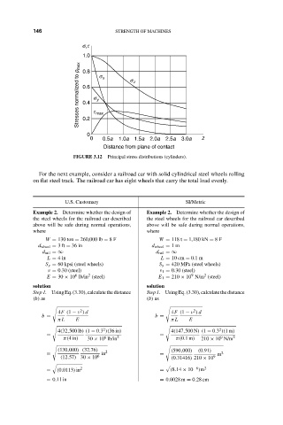
146
s,t
1.0 14:16 STRENGTH OF MACHINES
Stresses normalized to p max 0.6 t max s z
0.8
s x
s y
0.4
0.2
0
0 0.5a 1.0a 1.5a 2.0a 2.5a 3.0a z
Distance from plane of contact
FIGURE 3.12 Principal stress distributions (cylinders).
For the next example, consider a railroad car with solid cylindrical steel wheels rolling
on flat steel track. The railroad car has eight wheels that carry the total load evenly.
U.S. Customary SI/Metric
Example 2. Determine whether the design of Example 2. Determine whether the design of
the steel wheels for the railroad car described the steel wheels for the railroad car described
above will be safe during normal operations, above will be safe during normal operations,
where where
W = 130 ton = 260,000 lb = 8F W = 118 t = 1,180 kN = 8F
d wheel = 3ft = 36 in d wheel = 1m
d rail =∞ d rail =∞
L = 4in L = 10 cm = 0.1 m
S y = 60 kpsi (steel wheels) S y = 420 MPa (steel wheels)
ν = 0.30 (steel) ν 1 = 0.30 (steel)
9
6
2
2
E = 30 × 10 lb/in (steel) E 1 = 210 × 10 N/m (steel)
solution solution
Step1. UsingEq.(3.30),calculatethedistance Step1. UsingEq.(3.30),calculatethedistance
(b) as (b) as
2
2
4F (1 − ν ) d 4F (1 − ν ) d
b = b =
π L E π L E
2
2
4(32,500 lb) (1 − 0.3 )(36 in) 4(147,500 N) (1 − 0.3 )(1m)
= =
9
6
π(4in) 30 × 10 lb/in 2 π(0.1m) 210 × 10 N/m 2
(130,000) (32.76) 2 (590,000) (0.91)
= in = m 2
(12.57) 30 × 10 6 (0.31416) 210 × 10 9
$
%
= (0.0113) in 2 = (8.14 × 10 −6 )m 2
= 0.11 in = 0.0028 m = 0.28 cm