
Page 161 - Marks Calculation for Machine Design
P. 161
P1: Rakesh
January 4, 2005
14:16
Brown.cls
Brown˙C03
U.S. Customary ADVANCED LOADINGS SI/Metric 143
Step 3. As Poisson’s ratio (ν 1 ) for the titanium Step 3. As Poisson’s ratio (ν 1 ) for the titanium
wheels is close to the 0.3 used to graph the wheels is close to the 0.3 used to graph the
principal stress equations in Fig. 3.10, assume principal stress equations in Fig. 3.10, assume
the maximum shear stress occurs at 0.4a and is the maximum shear stress occurs at 0.4a and is
0.3 p max .Therefore,usingthevalueforthemax- 0.3 p max .Therefore,usingthevalueforthemax-
imum pressure found in Step 2, the maximum imum pressure found in Step 2, the maximum
shear stress (τ max ) is shear stress (τ max ) is
τ max = 0.3 p max = (0.3)(37.3 kpsi) τ max = 0.3 p max = (0.3)(243.6MPa)
= 11.2 kpsi = 73.1MPa
Step 4. Using Eq. (3.28), calculate the factor- Step 4. Using Eq. (3.28), calculate the factor-
of-safety (n) for the design as of-safety (n) for the design as
τ max 1 11.2 kpsi 2 (11.2) τ max 1 73.1MPa 2 (73.1)
= = = = 0.2 = = = = 0.2
S y n 110 kpsi 110 S y n 770 MPa 770
2 2 2 2
1 1
n = = 5 n = = 5
0.2 0.2
Clearly the design is safe. Clearly the design is safe.
3.3.2 Cylinders in Contact
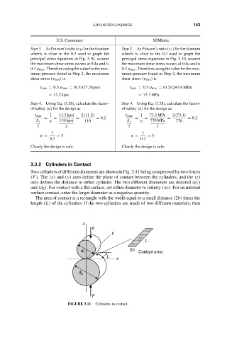
Two cylinders of different diameters are shown in Fig. 3.11 being compressed by two forces
(F). The (x) and (y) axes define the plane of contact between the cylinders, and the (z)
axis defines the distance to either cylinder. The two different diameters are denoted (d 1 )
and (d 2 ). For contact with a flat surface, set either diameter to infinity (∞). For an internal
surface contact, enter the larger diameter as a negative quantity.
The area of contact is a rectangle with the width equal to a small distance (2b) times the
length (L) of the cylinders. If the two cylinders are made of two different materials, then
z
F
y
L
d 1 2b Contact area
L
x
d 2
F
FIGURE 3.11 Cylinders in contact.