
Page 157 - Marks Calculation for Machine Design
P. 157
P1: Rakesh
January 4, 2005
14:16
Brown.cls
Brown˙C03
U.S. Customary ADVANCED LOADINGS SI/Metric 139
Step 4. As the minimum radial interface (δ min ) Step 4. As the minimum radial interface (δ min )
calculated from Step 2 is zero, the minimum calculated from Step 2 is very small, the mini-
interface pressure (p min ) is also zero. So, mum interface pressure (p min ) is
p min = 0 p min = 0
3.3 CONTACT LOADING
Contact loading occurs between machine elements such as rolling metal wheels, meshing
of gear teeth, and within the entire spectrum of bearings. The discussion on contact loading
will be divided into two main areas:
1. Spheres in contact
2. Cylinders in contact
In contact loading, an initial point (spheres) or line (cylinders) of contact develops into
an area of contact over which the load must be distributed. As these areas are typically very
small, the associated stresses can be quite large. The location of maximum stress can actually
occur below the surface of the machine element, causing catastrophic failure without prior
visible warning. For this reason, understanding the principles and stress equations that
follow are important to the machine designer.
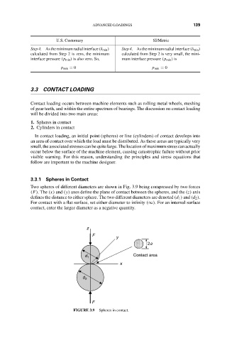
3.3.1 Spheres in Contact
Two spheres of different diameters are shown in Fig. 3.9 being compressed by two forces
(F). The (x) and (y) axes define the plane of contact between the spheres, and the (z) axis
defines the distance to either sphere. The two different diameters are denoted (d 1 ) and (d 2 ).
For contact with a flat surface, set either diameter to infinity (∞). For an internal surface
contact, enter the larger diameter as a negative quantity.
z
F
y
2a
d 1 Contact area
x
d 2
F
FIGURE 3.9 Spheres in contact.