
Page 155 - Marks Calculation for Machine Design
P. 155
P1: Rakesh
14:16
January 4, 2005
Brown.cls
Brown˙C03
d s ADVANCED LOADINGS d c 137
D hole
R
d shaft
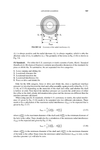
FIGURE 3.8 Geometry of the radial interference (δ).
(δ c ) is always positive and the radial decrease (δ s ) is always negative, which is why the
absolute value of (δ s ) is added to (δ c ). The geometry of the terms in Eq. (3.16) is shown in
Fig. 3.8.
Fit Standards. For either the U.S. customary or metric systems of units, Marks’ Standard
Handbook for Mechanical Engineers contains an exhaustive discussion of the standards for
press or shrink fits. To summarize, fits are separated into five categories:
1. Loose running and sliding fits
2. Locational clearance fits
3. Locational transition fits
4. Locational interference fits
5. Force or drive and shrink fits
Only for the fifth category, force or drive and shrink fits, does a significant interface
pressure (p) develop between the shaft and collar assembly, again given by either Eq. (3.13),
(3.14), or (3.15) depending on the materials of the shaft and collar, and whether the shaft
is hollow or solid. Note that if the interface pressure (p) exceeds the yield stress of either
the collar or the shaft, plastic deformation takes place and the stresses are different than the
interface pressure calculated.
When using specific fit standards, whether U.S. customary or metric, the radial interfer-
ence (δ) given by Eq. (3.16) needs to be separated into two different calculations. There
needs to be a calculation of the maximum radial interference (δ max ) to be expected that is
given by Eq. (3.17)
1 max min
δ max = d shaft − D hole (3.17)
2
where (d max ) is the maximum diameter of the shaft and (D min ) is the minimum diameter of
shaft hole
the hole in the collar. There should also be a calculation of the minimum radial interference
(δ min ) to be expected and given by Eq. (3.18),
1 min max
δ min = d shaft − D hole (3.18)
2
where (d min ) is the minimum diameter of the shaft and (D max ) is the maximum diameter
shaft hole
of the hole in the collar. Many times the minimum radial interference (δ min ) is zero, so the
interface pressure (p) will also be zero.