
Page 153 - Marks Calculation for Machine Design
P. 153
P1: Rakesh
14:16
January 4, 2005
Brown.cls
Brown˙C03
ADVANCED LOADINGS
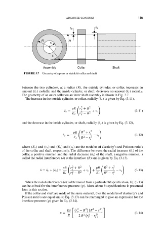
d c d s 135
R R
r i
r o
Assembly Collar Shaft
FIGURE 3.7 Geometry of a press or shrink fit collar and shaft.
between the two cylinders, at a radius (R), the outside cylinder, or collar, increases an
amount (δ c ) radially, and the inside cylinder, or shaft, decreases an amount (δ s ) radially.
The geometry of an outer collar on an inner shaft assembly is shown in Fig. 3.7.
The increase in the outside cylinder, or collar, radially (δ c ) is given by Eq. (3.11),
2
pR r + R 2
o
δ c = + ν c (3.11)
2
E c r − R 2
o
and the decrease in the inside cylinder, or shaft, radially (δ s ) is given by Eq. (3.12),
2
pR R + r i 2
δ s =− 2 2 − ν s (3.12)
E s R − r
i
where (E c ) and (ν c ) and (E s ) and (ν s ) are the modulus of elasticity’s and Poisson ratio’s
of the collar and shaft, respectively. The difference between the radial increase (δ c ) of the
collar, a positive number, and the radial decrease (δ s ) of the shaft, a negative number, is
called the radial interference (δ) at the interface (R) and is given by Eq. (3.13).
2
2
pR r + R 2 pR R + r 2 i
o
δ = δ c + |δ s | = 2 2 + ν c + 2 2 − ν s (3.13)
E c r − R E s R − r
o i
Whentheradialinterference(δ)isdeterminedfromaparticularfitspecification,Eq.(3.13)
can be solved for the interference pressure (p). More about fit specifications is presented
later in this section.
If the collar and shaft are made of the same material, then the modulus of elasticity’s and
Poisson ratio’s are equal and so Eq. (3.13) can be rearranged to give an expression for the
interface pressure (p) given in Eq. (3.14).
2
2
Eδ r − R 2 R − r 2 i
o
p = (3.14)
2
R 2 R 2 r − r i 2
o