
Page 298 - Marks Calculation for Machine Design
P. 298
P1: Shashi
15:4
January 4, 2005
Brown.cls
Brown˙C07
STRENGTH OF MACHINES
280
Each of these five factors will be discussed separately, then an example will be presented
to pull them together to provide an estimate of the endurance limit (S e ) for a particular
machine element design.
The first factor to discuss is the surface finish factor (k a ), probably the most important
of the five factors.
Surface Finish Factor. The surface finish of the R. R. Moore rotating-beam machine
test specimen is highly polished, particularly to remove any circumferential scratches or
marks that would cause premature failure and thereby corrupt the data. The actual machine
element under investigation may have a relatively rough surface finish, thereby providing a
place for a crack to develop, eventually leading to a fatigue failure.
The surface finish factor (k a ), therefore, depends on the level of smoothness of the surface
and the ultimate tensile strength (S ut ) and is given in Eq. (7.8) as
b
k a = aS ut (7.8)
where the coefficient (a) has units of stress and the exponent (b), which is negative and
dimensionless, are found in Table 7.1.
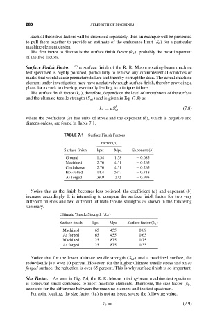
TABLE 7.1 Surface Finish Factors
Factor (a)
Surface finish kpsi Mpa Exponent (b)
Ground 1.34 1.58 − 0.085
Machined 2.70 4.51 − 0.265
Cold-drawn 2.70 4.51 − 0.265
Hot-rolled 14.4 57.7 − 0.718
As forged 39.9 272 − 0.995
Notice that as the finish becomes less polished, the coefficient (a) and exponent (b)
increase accordingly. It is interesting to compare the surface finish factor for two very
different finishes and two different ultimate tensile strengths as shown in the following
summary.
Ultimate Tensile Strength (S ut )
Surface finish kpsi Mpa Surface factor (k a )
Machined 65 455 0.89
As forged 65 455 0.63
Machined 125 875 0.75
As forged 125 875 0.33
Notice that for the lower ultimate tensile strength (S ut ) and a machined surface, the
reduction is just over 10 percent. However, for the higher ultimate tensile stress and an as
forged surface, the reduction is over 65 percent. This is why surface finish is so important.
Size Factor. As seen in Fig. 7.4, the R. R. Moore rotating-beam machine test specimen
is somewhat small compared to most machine elements. Therefore, the size factor (k b )
accounts for the difference between the machine element and the test specimen.
For axial loading, the size factor (k b ) is not an issue, so use the following value:
k b = 1 (7.9)