
Page 384 - Marks Calculation for Machine Design
P. 384
P1: Sanjay
January 4, 2005
Brown˙C08
Brown.cls
366
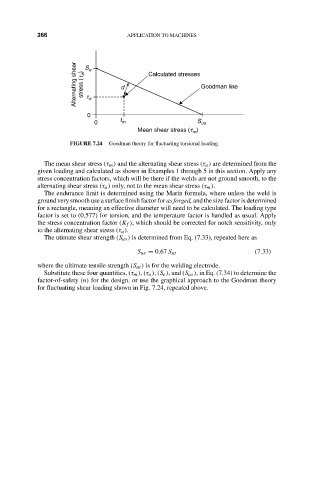
Alternating shear stress (t a ) S t a e 15:14 d APPLICATION TO MACHINES Goodman line
Calculated stresses
0
0 t m S us
Mean shear stress (t )
m
FIGURE 7.24 Goodman theory for fluctuating torsional loading.
The mean shear stress (τ m ) and the alternating shear stress (τ a ) are determined from the
given loading and calculated as shown in Examples 1 through 5 in this section. Apply any
stress concentration factors, which will be there if the welds are not ground smooth, to the
alternating shear stress (τ a ) only, not to the mean shear stress (τ m ).
The endurance limit is determined using the Marin formula, where unless the weld is
ground very smooth use a surface finish factor for as forged, and the size factor is determined
for a rectangle, meaning an effective diameter will need to be calculated. The loading type
factor is set to (0.577) for torsion, and the temperature factor is handled as usual. Apply
the stress concentration factor (K f ), which should be corrected for notch sensitivity, only
to the alternating shear stress (τ a ).
The utimate shear strength (S us ) is determined from Eq. (7.33), repeated here as
S us = 0.67 S ut (7.33)
where the ultimate tensile strength (S ut ) is for the welding electrode.
Substitute these four quantities, (τ m ),(τ a ),(S e ), and (S us ), in Eq. (7.34) to determine the
factor-of-safety (n) for the design, or use the graphical approach to the Goodman theory
for fluctuating shear loading shown in Fig. 7.24, repeated above.