
Page 386 - Marks Calculation for Machine Design
P. 386
P1: Naresh
January 4, 2005
15:28
Brown.cls
Brown˙C09
APPLICATION TO MACHINES
368
are cylindrical, though other shapes are also possible. The geometry of a cylindrical helical
spring with a circular cross section is shown in Fig. 9.1,
F
d
D
F
FIGURE 9.1 Geometry of a helical spring.
where (F) is the force on the spring, (D) is the mean spring diameter, and (d) is the wire
diameter. While it appears that the spring is merely under a compressive axial load due to
the two forces (F), the coils of the wire are actually under a combination loading of direct
shear and torsion. This can be seen if a cut is made through one of the coils, resulting in the
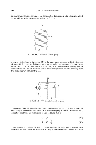
free-body-diagram (FBD) in Fig. 9.2.
F
d
T
V
D
FIGURE 9.2 FBD of a cylindrical helical spring.
For equilibrium, the shear force (V ) must be equal to the force (F), and the torque (T )
must be equal to the force (F) times (D/2), the mean spring diameter (D) divided by 2.
These two conditions are summarized in Eqs. (9.1) and (9.2) as
V = F (9.1)
D
T = F × (9.2)
2
The shear force (V ) and the torque (T ) each produce a shear stress over the circular cross
section of the wire. From the discussion in Chap. 5, the combination of these two shear