Page 379 - Marks Calculation for Machine Design
P. 379

P1: Sanjay
                                      15:14
                          January 4, 2005
        Brown.cls
                 Brown˙C08
                                        D o  MACHINE ASSEMBLY  L o        P       361
                                                 A
                                            r o    t torsion
                                L /2          t shear
                                 2
                             L 2
                                         O
                                          L 1


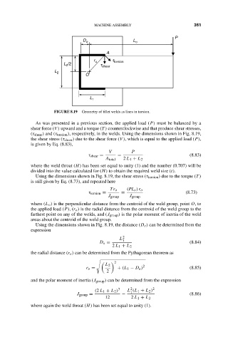
                             FIGURE 8.19  Geometry of fillet welds as lines in torsion.
                      As was presented in a previous section, the applied load (P) must be balanced by a
                    shear force (V ) upward and a torque (T ) counterclockwise and that produce shear stresses,
                    (τ shear ) and (τ torsion ), respectively, in the welds. Using the dimensions shown in Fig. 8.19,
                    the shear stress (τ shear ) due to the shear force (V ), which is equal to the applied load (P),
                    is given by Eq. (8.83),
                                                 V        P
                                          τ shear =  =                          (8.83)
                                                A total  2 L 1 + L 2
                    where the weld throat (H) has been set equal to unity (1) and the number (0.707) will be
                    divided into the value calculated for (H) to obtain the required weld size (t).
                      Using the dimensions shown in Fig. 8.19, the shear stress (τ torsion ) due to the torque (T )
                    is still given by Eq. (8.73), and repeated here
                                                  Tr o  (PL o )r o
                                          τ torsion =  =                       (8.73)
                                                 J group  J group
                    where (L o ) is the perpendicular distance from the centroid of the weld group, point O,to
                    the applied load (P),(r o ) is the radial distance from the centroid of the weld group to the
                    farthest point on any of the welds, and (J group ) is the polar moment of inertia of the weld
                    areas about the centroid of the weld group.
                      Using the dimensions shown in Fig. 8.19, the distance (D o ) can be determined from the
                    expression
                                                      L 2 1
                                              D o =                             (8.84)
                                                   2 L 1 + L 2
                    the radial distance (r o ) can be determined from the Pythagorean theorem as

                                                    2

                                                L 2           2
                                         r o =       + (L 1 − D o )             (8.85)
                                                 2
                    and the polar moment of inertia (J group ) can be determined from the expression
                                                          2
                                            (2 L 1 + L 2 ) 3  L (L 1 + L 2 ) 2
                                                          1
                                     J group =        −                         (8.86)
                                                12        2 L 1 + L 2
                    where again the weld throat (H) has been set equal to unity (1).
   374   375   376   377   378   379   380   381   382   383   384