Page 375 - Marks Calculation for Machine Design
P. 375

P1: Sanjay
                          January 4, 2005
                                      15:14
        Brown.cls
                 Brown˙C08
                                            MACHINE ASSEMBLY
                                      P
                                               H                       P          357
                                                        t
                                     L                      L o
                                  Front view             Side view
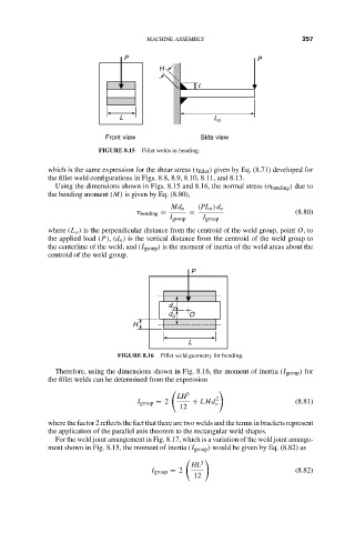
                                FIGURE 8.15  Fillet welds in bending.

                    which is the same expression for the shear stress (τ fillet ) given by Eq. (8.71) developed for
                    the fillet weld configurations in Figs. 8.8, 8.9, 8.10, 8.11, and 8.13.
                      Using the dimensions shown in Figs. 8.15 and 8.16, the normal stress (σ bending ) due to
                    the bending moment (M) is given by Eq. (8.80),
                                                  Md o  (PL o ) d o
                                         τ bending =  =                         (8.80)
                                                  I group  I group
                    where (L o ) is the perpendicular distance from the centroid of the weld group, point O,to
                    the applied load (P),(d o ) is the vertical distance from the centroid of the weld group to
                    the centerline of the weld, and (I group ) is the moment of inertia of the weld areas about the
                    centroid of the weld group.
                                                       P


                                                 d o
                                                 d o  O
                                         H
                                                      L
                                     FIGURE 8.16  Fillet weld geometry for bending.
                      Therefore, using the dimensions shown in Fig. 8.16, the moment of inertia (I group ) for
                    the fillet welds can be determined from the expression
                                                      3
                                                   LH
                                          I group = 2  + LHd o 2                (8.81)
                                                    12
                    where the factor 2 reflects the fact that there are two welds and the terms in brackets represent
                    the application of the parallel axis theorem to the rectangular weld shapes.
                      For the weld joint arrangement in Fig. 8.17, which is a variation of the weld joint arrange-
                    ment shown in Fig. 8.15, the moment of inertia (I group ) would be given by Eq. (8.82) as
                                                         3
                                                       HL
                                             I group = 2                        (8.82)
                                                       12
   370   371   372   373   374   375   376   377   378   379   380