Page 372 - Marks Calculation for Machine Design
P. 372

P1: Sanjay
                          January 4, 2005
                                      15:14
        Brown.cls
                 Brown˙C08
                                           APPLICATION TO MACHINES
                  354
                  and the polar moment of inertia (J group ) can be determined from the expression
                                                 3     3
                                               LH    HL       2
                                     J group = 2   +     + LHd o               (8.75)
                                               12     12
                  where the factor 2 reflects the fact that there are two welds and the terms in brackets represent
                  the application of the parallel axis theorem to the rectangular weld shapes.
                    Notice that the shear stress (τ shear ) acts downward at any point on either of the two welds;
                  however, the shear stress (τ torsion ) acts perpendicular to the radial distance (r o ). There are
                  four points, labeled (A), (B), (C), and (D) in Fig. 8.13, where the shear stress (τ torsion ) is
                  maximum. The maximum shear stress (τ max ) is therefore the geometric sum of these two
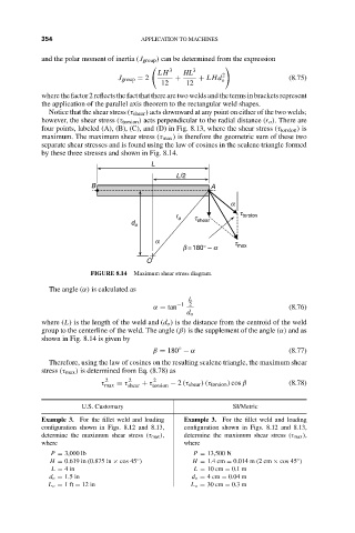
                  separate shear stresses and is found using the law of cosines in the scalene triangle formed
                  by these three stresses and shown in Fig. 8.14.
                                             L
                                                   L/2
                              B                             A
                                                                a
                                                                   t
                                                   r o  t          torsion
                                        d o             shear
                                              a                  t
                                                     b = 180° – a  max
                                            O
                              FIGURE 8.14  Maximum shear stress diagram.
                    The angle (α) is calculated as
                                                      L
                                              α = tan −1 2                     (8.76)
                                                      d o
                  where (L) is the length of the weld and (d o ) is the distance from the centroid of the weld
                  group to the centerline of the weld. The angle (β) is the supplement of the angle (α) and as
                  shown in Fig. 8.14 is given by
                                                    ◦
                                             β = 180 − α                       (8.77)
                    Therefore, using the law of cosines on the resulting scalene triangle, the maximum shear
                  stress (τ max ) is determined from Eq. (8.78) as
                                  2     2     2
                                 τ max  = τ shear  + τ torsion  − 2 (τ shear )(τ torsion ) cos β  (8.78)

                            U.S. Customary                       SI/Metric
                  Example 3. For the fillet weld and loading  Example 3. For the fillet weld and loading
                  configuration shown in Figs. 8.12 and 8.13,  configuration shown in Figs. 8.12 and 8.13,
                  determine the maximum shear stress (τ max ),  determine the maximum shear stress (τ max ),
                  where                              where
                     P = 3,000 lb                      P = 13,500 N
                                                                                ◦
                    H = 0.619 in (0.875 in × cos 45 )  H = 1.4 cm = 0.014 m (2 cm × cos 45 )
                                          ◦
                     L = 4in                           L = 10 cm = 0.1 m
                    d o = 1.5 in                       d o = 4cm = 0.04 m
                    L o = 1ft = 12 in                  L o = 30 cm = 0.3 m
   367   368   369   370   371   372   373   374   375   376   377