
Page 369 - Marks Calculation for Machine Design
P. 369
P1: Sanjay
15:14
January 4, 2005
Brown˙C08
Brown.cls
L
H MACHINE ASSEMBLY 351
t
P
P
Edge view Side view
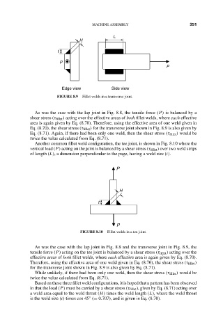
FIGURE 8.9 Fillet welds in a transverse joint.
As was the case with the lap joint in Fig. 8.8, the tensile force (P) is balanced by a
shear stress (τ fillet ) acting over the effective areas of both fillet welds, where each effective
area is again given by Eq. (8.70). Therefore, using the effective area of one weld given in
Eq. (8.70), the shear stress (τ fillet ) for the transverse joint shown in Fig. 8.9 is also given by
Eq. (8.71). Again, if there had been only one weld, then the shear stress (τ fillet ) would be
twice the value calculated from Eq. (8.71).
Another common fillet weld configuration, the tee joint, is shown in Fig. 8.10 where the
vertical load (P) acting on the joint is balanced by a shear stress (τ fillet ) over two weld strips
of length (L), a dimension perpendicular to the page, having a weld size (t).
P
H
t
P
FIGURE 8.10 Fillet welds in a tee joint.
As was the case with the lap joint in Fig. 8.8 and the transverse joint in Fig. 8.9, the
tensile force (P) acting on the tee joint is balanced by a shear stress (τ fillet ) acting over the
effective areas of both fillet welds, where each effective area is again given by Eq. (8.70).
Therefore, using the effective area of one weld given in Eq. (8.70), the shear stress (τ fillet )
for the transverse joint shown in Fig. 8.9 is also given by Eq. (8.71).
While unlikely, if there had been only one weld, then the shear stress (τ fillet ) would be
twice the value calculated from Eq. (8.71).
Based on these three fillet weld configurations, it is hoped that a pattern has been observed
in that the load (P) must be carried by a shear stress (τ fillet ), given by Eq. (8.71) acting over
a weld area equal to the weld throat (H) times the weld length (L), where the weld throat
is the weld size (t) times cos 45 (= 0.707), and is given in Eq. (8.70).
◦