
Page 371 - Marks Calculation for Machine Design
P. 371
P1: Sanjay
January 4, 2005
15:14
Brown.cls
Brown˙C08
P
L
H MACHINE ASSEMBLY P 353
t
Edge view Side view
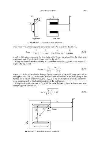
FIGURE 8.12 Fillet welds in shear and torsion.
shear force (V ), which is equal to the applied load (P), is given by Eq. (8.72),
V P P P
τ shear = = = = (8.72)
2 A fillet 2 (HL) 2 (0.707 t)( L) 1.414 tL
which is the same expression for the shear stress (τ fillet ) developed for the fillet weld
configurations in Figs. 8.8 to 8.11 and given by Eq. (8.71).
Using the dimensions shown in Fig. 8.13, the shear stress (τ torsion ) due to the torque (T )
is given by Eq. (8.73),
Tr o (PL o )r o
τ torsion = = (8.73)
J group J group
where (L o ) is the perpendicular distance from the centroid of the weld group, point O,to
the applied load (P),(r o ) is the radial distance from the centroid of the weld group to the
farthest point on any of the welds, and (J group ) is the polar moment of inertia of the two
weld areas (each H × L) about the centroid of the weld group.
Using the dimensions shown in Fig. 8.13, the radial distance (r o ) can be determined from
the Pythagorean theorem as
2
L
r o = + d o 2 (8.74)
2
P
L o
B A
r t
d o o t shear torsion
O
d o
H C D
L
FIGURE 8.13 Fillet weld geometry for torsion.