
Page 376 - Marks Calculation for Machine Design
P. 376
P1: Sanjay
15:14
January 4, 2005
Brown.cls
Brown˙C08
APPLICATION TO MACHINES
358
H
t P
×
P Top view
P
L
t L o
Front view Side view
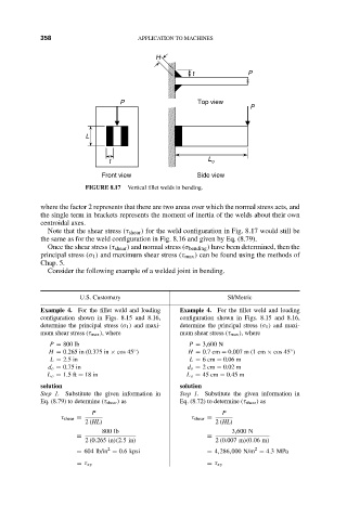
FIGURE 8.17 Vertical fillet welds in bending.
where the factor 2 represents that there are two areas over which the normal stress acts, and
the single term in brackets represents the moment of inertia of the welds about their own
centroidal axes.
Note that the shear stress (τ shear ) for the weld configuration in Fig. 8.17 would still be
the same as for the weld configuration in Fig. 8.16 and given by Eq. (8.79).
Once the shear stress (τ shear ) and normal stress (σ bending ) have been determined, then the
principal stress (σ 1 ) and maximum shear stress (τ max ) can be found using the methods of
Chap. 5.
Consider the following example of a welded joint in bending.
U.S. Customary SI/Metric
Example 4. For the fillet weld and loading Example 4. For the fillet weld and loading
configuration shown in Figs. 8.15 and 8.16, configuration shown in Figs. 8.15 and 8.16,
determine the principal stress (σ 1 ) and maxi- determine the principal stress (σ 1 ) and maxi-
mum shear stress (τ max ), where mum shear stress (τ max ), where
P = 800 lb P = 3,600 N
◦
H = 0.265 in (0.375 in × cos 45 ) H = 0.7 cm = 0.007 m (1 cm × cos 45 )
◦
L = 2.5 in L = 6cm = 0.06 m
d o = 0.75 in d o = 2cm = 0.02 m
L o = 1.5 ft = 18 in L o = 45 cm = 0.45 m
solution solution
Step 1. Substitute the given information in Step 1. Substitute the given information in
Eq. (8.79) to determine (τ shear ) as Eq. (8.72) to determine (τ shear ) as
P P
τ shear = τ shear =
2 (HL) 2 (HL)
800 lb 3,600 N
= =
2 (0.265 in)(2.5in) 2 (0.007 m)(0.06 m)
2
2
= 604 lb/in = 0.6 kpsi = 4,286,000 N/m = 4.3MPa
= τ xy = τ xy