
Page 378 - Marks Calculation for Machine Design
P. 378
P1: Sanjay
January 4, 2005
Brown˙C08
Brown.cls
360
U.S. Customary 15:14 APPLICATION TO MACHINES SI/Metric
Step 6. Substitute the average stress (σ avg ) Step 6. Substitute the average stress (σ avg )
from step 4 and the maximum shear stress from step 4 and the maximum shear stress
(τ max ) from step 5 in Eq. (5.15) to determine (τ max ) from step 5 in Eq. (5.15) to determine
the principal stress (σ 1 ) as the principal stress (σ 1 ) as
σ 1 = σ avg + τ max σ 1 = σ avg + τ max
= (7.15 kpsi) + (7.18 kpsi) = (47.8MPa) + (48.0MPa)
= 14.32 kpsi = 95.8MPa
Note that the contribution from the shear stress (τ shear ) in the calculations for the principal
stress (σ 1 ) and the maximum shear stress (τ max ) was almost negligible compared to the
normal stress (σ bending ). This is typical of these kinds of weld joint configurations and
loadings.
8.3.4 Fillet Welds Treated as Lines
In Examples 1 through 4, the weld throat (H) was specified as part of the given information,
determined from a weld size (t). However, in practice the weld size may be the primary
unknown. Therefore, it is convenient to set the weld throat (H) equal to unity (1) in the
expressions for the weld area, (A butt ) or (A fillet ), the polar moment of inertia (J group ), and
the moment of inertia (I group ) so that in the calculations for the stresses the units are stress
times a unit width, that is, (kpsi-in) or (MPa-m). Once an appropriate weld strength (S weld )
is specified, dividing this strength into the calculated stress will give a value for the size of
weld throat (H), from which a weld size (t) can be found.
There are sets of tabulated formulas for the weld areas and moments of inertia of various
weld configurations in any number of references, such as Marks’ Standard Handbook for
Mechanical Engineers. However, to show how setting the weld throat (H) to unity (1)
allows the designer to determine the required weld size (t), consider the following variation
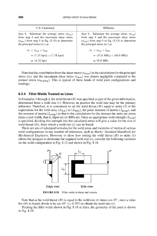
on the weld configuration in Fig. 8.12 and shown in Fig. 8.18.
P L 1 P
H
t
L 2
Edge view Side view
FIGURE 8.18 Fillet welds in shear and torsion.
Note that as the weld throat (H) is equal to the weld size (t) times cos 45 , once a value
◦
for (H) is found, divide it by cos 45 (= 0.707) to obtain the weld size (t).
◦
Treating the fillet welds shown in Fig. 8.18 as lines, the geometry of the joint is shown
in Fig. 8.19.