
Page 366 - Marks Calculation for Machine Design
P. 366
P1: Sanjay
January 4, 2005
Brown˙C08
Brown.cls
348
U.S. Customary 15:14 APPLICATION TO MACHINES SI/Metric
Summarizing, Summarizing,
n load = 1.78 < 2 n load = 1.87 < 2
n separation = 5.9 ∼ 6 n separation = 6.5
=
n fatigue = 2.4 n fatigue = 2.4
n yield = 1.13 n yield = 1.15
Only the factor-of-safety against yielding Only the factor-of-safety against yielding
(n yield ) should be of concern. (n yield ) should be of concern.
8.3 WELDED CONNECTIONS
Again, as the overall theme of this book is to uncover the mystery of the formulas used
in machine design for the practicing engineer, it will be assumed that the details of the
nomenclature of welds and the standards of the American Welding Society (AWS) are
unnecessary. Therefore the discussion will proceed directly to the first important topic for
the designer, welded joints in axial and transverse loading.
8.3.1 Axial and Transverse Loading
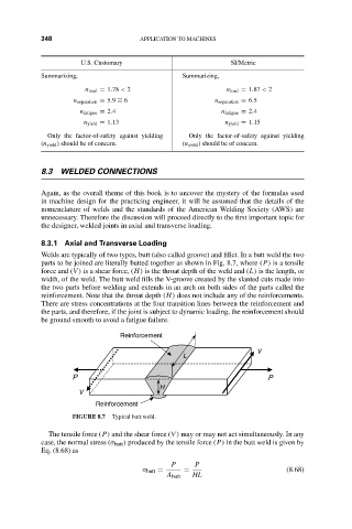
Welds are typically of two types, butt (also called groove) and fillet. In a butt weld the two
parts to be joined are literally butted together as shown in Fig. 8.7, where (P) is a tensile
force and (V ) is a shear force, (H) is the throat depth of the weld and (L) is the length, or
width, of the weld. The butt weld fills the V-groove created by the slanted cuts made into
the two parts before welding and extends in an arch on both sides of the parts called the
reinforcement. Note that the throat depth (H) does not include any of the reinforcements.
There are stress concentrations at the four transition lines between the reinforcement and
the parts, and therefore, if the joint is subject to dynamic loading, the reinforcement should
be ground smooth to avoid a fatigue failure.
Reinforcement
V
L
P P
H
V
Reinforcement
FIGURE 8.7 Typical butt weld.
The tensile force (P) and the shear force (V ) may or may not act simultaneously. In any
case, the normal stress (σ butt ) produced by the tensile force (P) in the butt weld is given by
Eq. (8.68) as
P P
σ butt = = (8.68)
A butt HL