
Page 368 - Marks Calculation for Machine Design
P. 368
P1: Sanjay
January 4, 2005
Brown˙C08
Brown.cls
350
U.S. Customary 15:14 APPLICATION TO MACHINES SI/Metric
determine the maximum shear stress (τ max ) as determine the maximum shear stress (τ max ) as
2 2
σ xx − σ yy 2 σ xx − σ yy 2
τ max = + τ xy τ max = + τ xy
2 2
2 2
(1.6) − (0) (11.25) − (0)
2
2
= + (1.2 ) kpsi = + (8.44 ) MPa
2 2
= (0.64) + (1.44 ) kpsi = (31.64) + (71.23 ) MPa
√ √
= 2.08 kpsi = 1.44 kpsi = 102.87 kpsi = 10.14 MPa
Step 5. Substitute the average stress (σ avg ) Step 5. Substitute the average stress (σ avg )
from step 3 and the maximum shear stress from step 3 and the maximum shear stress
(τ max ) from step 4 in Eq. (5.15) to determine (τ max ) from step 4 in Eq. (5.15) to determine
the principal stress (σ 1 ) as the principal stress (σ 1 ) as
σ 1 = σ avg + τ max σ 1 = σ avg + τ max
= (0.8 kpsi) + (1.44 kpsi) = (5.63 MPa) + (10.14 MPa)
= 2.24 kpsi = 15.77 MPa
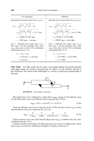
Fillet Welds. For fillet welds, the two parts to be joined together are placed such that
right-angle corners are created as shown in Fig. 8.8, where (t) is the weld size and (H) is
the weld throat. Not shown is the weld length (L), which is a dimension perpendicular to
the page.
H
t
P
t
P
FIGURE 8.8 Fillet welds for a lap joint.
The tensile force (P) is balanced by a shear stress (τ fillet ) acting over the effective areas
of both fillet welds, where each effective area is given by Eq. (8.70) as
◦
A fillet = HL = (t cos 45 ) L = 0.707 tL (8.70)
Using the effective area of one weld given in Eq. (8.70), the shear stress (τ fillet ) for the
lap joint shown in Fig. 8.8 is given by Eq. (8.71) as
P P P P
τ fillet = = = = (8.71)
2 A fillet 2 (HL) 2 (0.707 t)( L) 1.414 tL
If there had been only one weld, then the shear stress (τ fillet ) would be twice the value
calculated from Eq. (8.71).
Consider the fillet welds in Fig. 8.9 where the transverse load (P) is balanced by a shear
stress (τ fillet ) over the two weld strips of length (L) having a weld size (t).