
Page 370 - Marks Calculation for Machine Design
P. 370
P1: Sanjay
January 4, 2005
15:14
Brown.cls
Brown˙C08
352
APPLICATION TO MACHINES
Consider the following example.
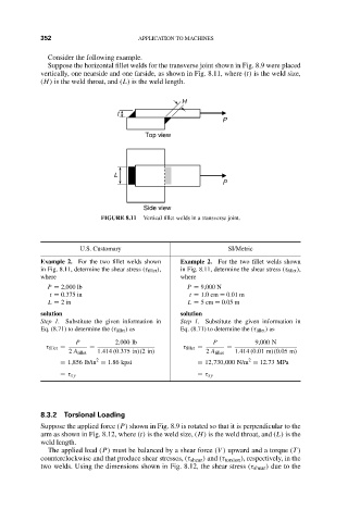
Suppose the horizontal fillet welds for the transverse joint shown in Fig. 8.9 were placed
vertically, one nearside and one farside, as shown in Fig. 8.11, where (t) is the weld size,
(H) is the weld throat, and (L) is the weld length.
H
t
P
Top view
L
P
Side view
FIGURE 8.11 Vertical fillet welds in a transverse joint.
U.S. Customary SI/Metric
Example 2. For the two fillet welds shown Example 2. For the two fillet welds shown
in Fig. 8.11, determine the shear stress (τ fillet ), in Fig. 8.11, determine the shear stress (τ fillet ),
where where
P = 2,000 lb P = 9,000 N
t = 0.375 in t = 1.0 cm = 0.01 m
L = 2in L = 5cm = 0.05 m
solution solution
Step 1. Substitute the given information in Step 1. Substitute the given information in
Eq. (8.71) to determine the (τ fillet ) as Eq. (8.71) to determine the (τ fillet ) as
P 2,000 lb P 9,000 N
τ fillet = = τ fillet = =
2 A fillet 1.414 (0.375 in)(2in) 2 A fillet 1.414 (0.01 m)(0.05 m)
2
2
= 1,856 lb/in = 1.86 kpsi = 12,730,000 N/m = 12.73 MPa
= τ xy = τ xy
8.3.2 Torsional Loading
Suppose the applied force (P) shown in Fig. 8.9 is rotated so that it is perpendicular to the
arm as shown in Fig. 8.12, where (t) is the weld size, (H) is the weld throat, and (L) is the
weld length.
The applied load (P) must be balanced by a shear force (V ) upward and a torque (T )
counterclockwise and that produce shear stresses, (τ shear ) and (τ torsion ), respectively, in the
two welds. Using the dimensions shown in Fig. 8.12, the shear stress (τ shear ) due to the