
Page 454 - Marks Calculation for Machine Design
P. 454
P2: Sanjay
P1: Shibu/Rakesh
15:34
January 4, 2005
Brown˙C10
Brown.cls
APPLICATION TO MACHINES
436
1
Cable
P
v P
2
v W
W (load)
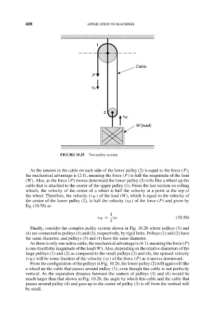
FIGURE 10.25 Two pulley system.
As the tension in the cable on each side of the lower pulley (2) is equal to the force (P),
the mechanical advantage is (2:1), meaning the force (P) is half the magnitude of the load
(W). Also, as the force (P) moves downward the lower pulley (2) rolls like a wheel up the
cable that is attached to the center of the upper pulley (1). From the last section on rolling
wheels, the velocity of the center of a wheel is half the velocity at a point at the top of
the wheel. Therefore, the velocity (v W ) of the load (W), which is equal to the velocity of
the center of the lower pulley (2), is half the velocity (v P ) of the force (P) and given by
Eq. (10.58) as
1
v W = v P (10.58)
2
Finally, consider the complex pulley system shown in Fig. 10.26 where pulleys (3) and
(4) are connected to pulleys (1) and (2), respectively, by rigid links. Pulleys (1) and (2) have
the same diameter, and pulleys (3) and (4) have the same diameter.
As there is only one active cable, the mechanical advantage is (4:1), meaning the force (P)
is one-fourth the magnitude of the load (W). Also, depending on the relative diameters of the
large pulleys (1) and (2) as compared to the small pulleys (3) and (4), the upward velocity
(v W ) will be some fraction of the velocity (v P ) of the force (P) as it moves downward.
From the configuration of the pulleys in Fig. 10.26, the lower pulley (2) will again roll like
a wheel up the cable that passes around pulley (3), even though this cable is not perfectly
vertical. As the separation distance between the centers of pulleys (3) and (4) would be
much larger than that shown in Fig. 10.26, the angle by which this cable and the cable that
passes around pulley (4) and goes up to the center of pulley (3) is off from the vertical will
be small.